The cassette speed control looks fairly complicated, but I spose the recorder is a higher end one, and motor speed control is a critical part of the system to avoid wow & flutter.
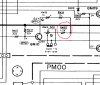
Looks like the board for the tape motor is seperate, 'PM00'. There is a chip that looks like it an amp of some kind QM01, looks like theres a fine tuning pot on this.
Only guessing but I'd say that chip QM08 is the main speed control, probably a phase or frequency locked loop, it gets pulses from QM07 some kind of pulse generator either in the motor itself or on the deck somewhere, the phase locked loop will adjust the sped voltage output to match the frequency of the pulse generator with that of a built in oscillator.
Without actual chip numbers its not possible to go any further, also the chip numbers may well be house coded devices as theres no specific info on the schematic.
You could try adjusting RM04, mark the original position first, and see how much control that has and whether its enough, I suspect it will not have much range, you might be able to increase its range by replacing RM03, the only thing is if you change RM03 for too small a value you might blow the chip.

")