Continue to Site

Welcome to our site!

Electro Tech is an online community (with over 170,000 members) who enjoy talking about and building electronic circuits, projects and gadgets. To participate you need to register. Registration is free. Click here to register now.

  • Welcome to our site! Electro Tech is an online community (with over 170,000 members) who enjoy talking about and building electronic circuits, projects and gadgets. To participate you need to register. Registration is free. Click here to register now.

cascading trouble 3d LED audio spectrum analyser

Status
Not open for further replies.

rhl.thakur

New Member
hi
im a complete newbie so im really confused abt this. ne help would be really appriciated.

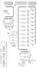
I have a 10 bandpass audio spectrum analyser design (10x10 LED). I understand it pretty well(i guess) and i there is no problem there.( Thnx to the Vietnamese guy)

The output of filters are connected with switches(transistors) which are connected with output of 4017 in parallel which also acts as a switch for the +5v for the LED matrix (Y axis). The signal from the filter(one at an instant, corresponding to the output of 4017) is fed to LM3914N which evaluates and gives the output on the X axis. I understand that the circuit is multiplexed.

The problem is that i want to extend it in to a 3D cuboid type of design (10x10x15). I was hoping that i could generate a wave kind of effect. I hv considered cascading 4017 but got really confused.

If ne one can guide me in the right direction it would be really helpful.

Thanx in advance.
 

Attachments

  • Oscilator Counter & Vu Meter.jpg
    Oscilator Counter & Vu Meter.jpg
    526.9 KB · Views: 1,298
The datasheet for the CD4017 by many manufacturers shows how to cascade them.
The Vietnamese audio spectrum analyser project is multiplexed which makes the LEDs appear dim. One end of each LED is fed the max allowed current from an LM3914 (but it should be an LM3915) which is 30mA and when multiplexed each LED gets an average of only 3mA which is dim.
 
Currently, you have frequency and the relative level as data to be displayed. What would the third axis of the cube represent?

Also, it's best to type out the whole word rather than to use abbreviations such as "abt", "ne", or "hv". That tends to irritate other forum members.
 
I am sorry

Thanks Jbeng

Sorry about the abbreviations.

The X axis shows the frequency divided into 10 columns.
The Y axis shows the strength of the signal (audio) in that frequency range.
The Z axis would be that of time.

The strength indicated on the 10x10 matrix in the front would be carried to the one behind it, and a new spectrum graph would be genarated on the first matrix.
The 2nd moves to the 3rd n so on until 15th where it is discarded after being displayed.

I hope this clears what i have in mind.

Thanks again
 
Last edited:
Thanks Audioguru

So what do you suggest? How do i get them to be bright without a complete change of schematics. Also i am running 3x3x3 LED Cube off Arduino Mega, inspite of being multiplexed it still seems very bright...! is this due to the low LED count?

Thanks for suggesting LM3915.
Cascading is not a problem, the problem is how to connect it to the analyser?
I was planning to connect 2x4017( cascaded ) to every column of analyser. But as far as i can calculate this will not solve my purpose as i can drive a pulse thorugh the columns (Z axis) but the strength (X Axis) wont be available.

Am i thinking in the right direction?

Thanks
 
So what do you suggest? How do i get them to be bright without a complete change of schematics. Also i am running 3x3x3 LED Cube off Arduino Mega, inspite of being multiplexed it still seems very bright...! is this due to the low LED count?
Cheap chinese LEDs apper bright because they focus the light beam into a very narrow angle. But then the LEDs are barely visible a little off to the side.

Thanks for suggesting LM3915.
The logarithmic response of the LM3915 matches the logarithmic response of our hearing to sound levels.
The LM3914 is a linear voltmeter.

Cascading is not a problem, the problem is how to connect it to the analyser?
I don't know how to add a "depth" ability to the multiplexed display.
 
Status
Not open for further replies.

Latest threads

New Articles From Microcontroller Tips

Back
Top