Continue to Site

Welcome to our site!

Electro Tech is an online community (with over 170,000 members) who enjoy talking about and building electronic circuits, projects and gadgets. To participate you need to register. Registration is free. Click here to register now.

  • Welcome to our site! Electro Tech is an online community (with over 170,000 members) who enjoy talking about and building electronic circuits, projects and gadgets. To participate you need to register. Registration is free. Click here to register now.

Capacitor type and value for circuit

Status
Not open for further replies.

quintessential

New Member
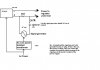
hello, so i have this circuit(suggested by friends on this forum) that provides me a DC voltage supply superimposed on an AC voltage supply. The DC supply is great but i'm trying to get a frequency rersponse of the AC signal up to 10MHZ.The key is the capacitor in the circuit.It is what couples the AC and DC sources together but as you can see it creates a filter that slightly attenuates my AC signal.Basically i'm asking if anyone is savvy with capacitors and can offer a suggestion as to the type(electrolytic,ceramic.....) and value(10pF 100nF) that would give me the best and widest frequency response.
 

Attachments

  • pop-pop.JPG
    pop-pop.JPG
    37 KB · Views: 163
What is the lowest AC signal you want to couple? If it is in the audio range and you want to go all the way up to 10Mhz, you can put some ceramic caps in parallel with a electrolytic to form a cap that will work across such a wide bandwidth (Say 1000pf, 0.01uf, 0.1uf and 47uf). Or use a tantalum cap, though you'd have to check the spec's to see if the particular one you have will work properly to 10Mhz.
 
kchriste said:
What is the lowest AC signal you want to couple? If it is in the audio range and you want to go all the way up to 10Mhz, you can put some ceramic caps in parallel with a electrolytic to form a cap that will work across such a wide bandwidth (Say 1000pf, 0.01uf, 0.1uf and 47uf). Or use a tantalum cap, though you'd have to check the spec's to see if the particular one you have will work properly to 10Mhz.

i'm going to try the circuit with the lowest singe capacitance value tantalum cap i can find. you just confirmes past research that Tantalum caps work best for AC coupling and DC blocking type circuits.
then i'll try it with a capacitance network as you suggested.As for The mix of ceramic and electrolytic caps to form a wide bandwidth cap,does this work
a)due to their inherent nature
b)due to the range of cap values
c)both a) and b)
Hopefully something will come close to my target of flatband response from DC to 10mHz.
 
quintessential said:
Hopefully something will come close to my target of flatband response from DC to 10mHz.

Making something flat from DC to 10MHz isn't trivial to start with - but I suggest you tell us EXACTLY what you're wanting to do, as opposed to how you think it should be done. As it stands I don't have the faintest idea what you're on about?.
 
quintessential said:
As for The mix of ceramic and electrolytic caps to form a wide bandwidth cap,does this work
a)due to their inherent nature
b)due to the range of cap values
c)both a) and b)
Hopefully something will come close to my target of flatband response from DC to 10mHz.
The answer is A. Electrolytics don't work very well at high frequencies but ceramic caps do. Ceramic caps also have self resonance points due to lead inductance so adding different ones in parallel will tend to swamp this effect. But I wouldn't worry too much about it being totally flat anyway since you can compensate by adjusting the signal generator output while monitoring the ripple on the DC input to the regulator.
Nigel Goodwin said:
As it stands I don't have the faintest idea what you're on about?
It is related to this thread:
https://www.electro-tech-online.com/threads/what-op-amp-to-use.31477/
 
Status
Not open for further replies.

Latest threads

New Articles From Microcontroller Tips

Back
Top