Continue to Site

Welcome to our site!

Electro Tech is an online community (with over 170,000 members) who enjoy talking about and building electronic circuits, projects and gadgets. To participate you need to register. Registration is free. Click here to register now.

  • Welcome to our site! Electro Tech is an online community (with over 170,000 members) who enjoy talking about and building electronic circuits, projects and gadgets. To participate you need to register. Registration is free. Click here to register now.

Capacitor discharge welder

Status
Not open for further replies.
Hello Shortbus.

I'm happy , having a " learn something new every day" to you .
I have seen nowhere a spotwelder for aluminium with discharge of capacitors and MOSFET power/driver ...(flat calm on the market ),... for this kind of material .
But this sort of material would be very interessing for electronicians as me , to build box in aluminium for amplifacators , power supply and so on ...
For cars factories I suppose that would be interested so , .
In France in the years 60/70 a constructor "Panhard" build a car the "Dina Panhard: PL 17 and PL 19 " completly in aluminium , but fixed with rivets and screws, it was a little noisy after many years of use ...
A very light car with a light motor , and with a consumption low for this period .

For electronicians :

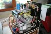
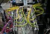
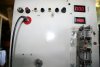
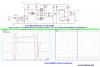
I send sooner my scheme of my driver able to drive current up to 100 Ampères pic for 50 to 100 MOSFET in //...others shemes of my welder prototyp are ( for me ) without interest .

At +
Jac.
 
Last edited:
Hello.

My driver for MOSFET in // as here simulated With IRF4468... IRF3711 , have the same max current but only with 20 V , V DS ..
Attention , this driver is particular for my prototyp , because of the max dI/dt by MOSFET (100A/µs) the 2 capacitors on the gate get down to the ground , making a t"on" and t "off " of 1.5µs ...it's slow for a driver in Buck or other form cutting power supply under 100 or 200 kHz .
In a normal use this capacitors are in // with the gate résistor .

For a limit rise and slope , the 2 out résistors coming from the MOSFET driver are just Under 1 Ohm ( 0.1 to 0.2 Ohms in my case).

In a normal use for drive quickly ,Under 100ns , these one can be adjust at 10 to 20 mOhms .

By.

Jac.
 

Attachments

  • driver de mosfet sept 2018.jpg
    driver de mosfet sept 2018.jpg
    763.2 KB · Views: 106
Last edited:
Jacounet, don't know if this would work or not but just an idea to put out there. How about a two stage welder? By that I mean the first stage would be AC to both clean and preheat the Aluminum, that stage controlled with a triac. Then after the cleaning stage, that would be timed, then a capacitor dump for the second stage, to make the actual weld. Like said just an idea.
 
Hello Shorbus.

I have not made on PCB this scheme ...but it's OK with simulation ...is it the same in the true live , to verifie of course ...

Yes this process in 2 part , a preheat/ prewarm make the resistor climb at 4 times the cold resistor just before the fusion ... that give a best efficiency for the second part ...if it's a process by discharge of capacitor .

I have make a scheme last week with a SCR on the secondary of a transformer 230 V /2 V, and we can selecte on the gate of the SCR ,softwares made with a CD4040 binary counter , 1 of 2 periodes , 2 of 4 périodes , 4 of 8 périodes, 8 of 16 périodes ,16 of 32 périodes of 50 Hz ...on 1.5 second soldering.

I have bought last month a SCR in China it's a 2500A/1600 V ...it would be OK for this work.
Convenient ,..we make a call of current on "+" half periode or on "-" half periode following the position of the SCR on the out put of the transformer ...=> making a saturation after many impulses in the same magnetic direction .
Except this defect , I think it can " badly" work .
I can try it this process on my DIY spotwelder with 1 secondary turm of 535 mm2. ( I named my DIY spot welder : "EGM" => Equivalent Gros moche in french).

That all for today .

Jac.
 
Last edited:
Shortbus, yes as you kinda mentioned I'm fairly sure ally spotters work a bit like ally welders, the weld current comes from a fet bridge and Ac is used to clean & weld.
I have maintained steel spotters, these were 4 stage, pre squeeze without weld current, pre weld on low weld current, main weld high weld current, then finally solidify, where the electrodes hold the work with no weld current long enough for the joint to stick together.
Obviously these sets has pneumatic cylinders to squeeze the work.
Dont know how you'd do this jaco, maybe 2 cap banks for 2 stages.
If your caps are very low esr and esl, and you have heavy weld leads you might want a small (in value) inductor to limit di/dt and prevent blowing your scr's.
 
Hello.dr Pepper.

I have make an order in China for 2 supercapacitors 500F/2.7 V , a possibility of 3645 Joules...and 50xMOSFET IRFR3711.
In my first projet I will want to use N MOSFET in pararel , exactly 50xIRFR371 ( 93 A/20V ) in //.
Before that , I have make 3 tries Under 80/90 V with 20 IXYS 100V/100A , I make a hope on the max current 540A by MOSFET during 100µs==> it was not a good deal/solution ...no soldering...and some NMOS fused.
Then I have make others tries Under 20V, with 20x IRFP4468 in //...no succes , no soldering .
I have suspected many things the:
- dI/dt in command and in power out ...so I have put in serial an inductor of 100nH , an enought value on Spice for make a dI/dt Under 100A/µs.
-then the "-dphi/dt " ...
-then the lower resistor Under soldering ( 200µ Ohm in min , and 800µ Ohm in max ) making a hight intensity upper 5000A.
So I will make the others tries Under 2.7 V ...
My calculations in this case , seams to be more respectfull of the reality .==> a max intensity Under 4500A.
Recall: 2 V on Capacitor ,Under 0.5 m Ohm for solder ==> give 4000A max .
With 50x IRFR371 the max possibility is 50x93=4650 A...continuousely.
The serial inductor is 22 n H...it's low enought for not eat energy , and up enougt to calm the dI/dt under 100A/µs , if I refered to ISIS Spice model .

The ESR of the supercapacitor 2x 500F in // is Under 0.1 m Ohm (if I well read ) , the r DS "on" of 50xMSFET in //= 5 mOhms/50=0.1 m Ohm.

I hope no mistake for the next tries .

The SCR solution will be the last trie , if no succes with N MOSFET .

If somebody interested I make a photography of my prototype ...it's not a beautifull one , but if it work , correctly one day ...:)

Jac.
 
Last edited:
I use to work in the spot welding department of a big factory 45 years ago. We used an NL-7171 Ignitron Tube as a switch. Spot welder clamps the metal part very hard and hold pressure then the tube sent power from spot welder transformer 1 volts, 5000 amps to the welding tops. There was a timer dial to set the time it welded. Turn up the time to get a perfect weld. If time is too short metal is not welded very strong. If time is too long it burns a hole in the metal. You dial in the time example maybe 7/10 of a second works good so that is where you leave it. If welding tips burn down diameter gets larger so either tips need to be repaired or change time to 8/10 of a second or 9/10 of a second until it welds good again. I don't think you can get 7/10 of a second with a capacitor bank, maybe you can if you can slow down the capacitor bank so it discharges slower. You need to buy a 1500 amp 600 volt industrial mosfet to experiment with IGBT about $100 each on ebay.
 
Last edited:
Hello Garry.
Yes that's right , the Ignitron , the ancestor of SCR...(thyristor in french).:cool:
Your spot welder from your factory work , can weld aluminium I suppose , because you speak of hole in the metal ...it's a caracteristic of too hot welding on aluminium.
My solution for the moment : a supercapacitor 1000F/2.7 V able to provide an energy of 3645 Joules.
It's enought , if my calculations are correct to fuse/weld 2 sheets 2 x2 mm of aluminium ...timing will be to trie by experience.
My "research" ...at this "t" time is to switch the power with MOSFET in parallel 50 "IRFR3711" exactly .
My first tries was unsuccessfull ...because of intensity out off limits for my MOSFET ( 20 in // , then 32 in //...in many tries ) .
But I think the way ==> MOSFET N by 50xin // are able to switch 4650 A (93 each X50) during appropriates times is a good one .

As I say to dr Pepper yesterday , I keep a last cartridge ..a 2500A/1600 V SCR, that I have bought this summer from China for less than 100 USD.
IGBT and MOSFET are around 200 Ampères max by unit for the best in intensity ...as I have read on the net and else...
On the market ,we have module IGBT and MOSFET ( it's paralel MOS and IGBT made in factory) , but lower than 1000 Amperes , and the price is not for "retires" as us .
If you have best informations , you can send me that .

Best regards .

Jac.
 
Last edited:
Sounds like you have it sorted jaco.
Back in the 90's I upgraded a british fedaral spotter that had ignatrons to thyristors.
Some Bf sets used plug in numbers to set the timings, they were gold dust, there was never enough of one number.
 
Part number CH600HA-24H

These are basically bullet proof for us hobby people you will have a very hard time killing one of these. Check data sheet online I don't remember the details I want to say, 600v 1500a trigger = about 20v maximum but look it up don't take my word for it.

EBay prices are down here is a link to 1 for $28 do a search you will fine others for sale. This one has no metric bolts for attaching wires but you can buy those at any hardware store about 20¢ each.

I have a box full of wire terminals rated 30 amps to about 800 amps all sizes. I have been planning to sell the whole lot on ebay but been putting it off for 6 years I have totally lost interest in ebay you could use a few of these for your project. They don't cost much if you only need a few.

It is hard for me to get short pieces of high amp wire unless I can find some at the scrap metal yard. I bought a 500 ft roll of #14 solid copper ground wire with no insulation cut about 20 pieces to the same length use heat shrink tubing or wire ties to make your own high amp wires any amp rating you need. 20 pieces of #14 = 300 amps.

Flat Copper straps work great for high amps too, buy roofing copper cut it into 1" wide strips put 10 of those together drill a bolt hole on each end.

https://www.ebay.com/itm/MITSUBISHI...:Q60AAOSwzyBbjYSH:sc:USPSPriority!37129!US!-1
 
Last edited:
Hello Garry 350.

The CH600HA-24H of Mitsubishi ( or CM600HA-24H) , can pass continuously a current of 600 A Under 1200 Volts .
It's an interessing product for hight power but working with a receptor with an resistor/impedance upper than 2 Ohms...if used Under 1200 V.

But it can't provide a hight power with a very very low resistor as 2 sheets of aluminium of 2 mm thik under points of 1 mm diameter.===>= 800 µ ohm.
Excepted if you make a huge sinusoidal oscillator ( 10 to 100 kWatts) with this sort of IGBT ...that was the choice of the factory Matsuchek ( upper dicted in the first page) ,...oscillator Under 20 kHz using a huge transformer with 1 secondary winding...and certainly 2 SCR in a primary with a middle point , for swiche the power , in this case not limited by the deathly 200A/µs of the silicium wafer.
This kind of project with a "mega" oscillator , is a little "off" the DIY possibility ..but possible for an electronician with perhap's ...500 to 1000 USD of economy ...for that.
I'm the first one , but not the second .

I search the CH600HA-24 H on the net, I have found the CM600HA-26 H data sheets , perhap's the same , ...but the price is 50.32 USD with shipping ...
If I want 4000 Ampères of current it's a lot of x 7 pieces, or more that I need ...giving ==>350 USD, ...280 €...it's a little "off" budget .

If my 50 xIRFR3711, coming from China , with a cost of 15€ for the lot , can make the same job , why not ...:meh:


A+.

Jac
 
Last edited:
Hello.

For giving some live for this subject this is some phtography of my prototype .
It was like this last month , Ihave made some change , the blue coil have only one turn now and is only 22 nH ...and I add one resistor of 2 milliOhms in each drain of MOSFET.
The target is to trie to distribute eqally the current in each MOSFET , a detail each MOSFET have a rDS"on" of 5 mOhms .
On face you have 2 digital voltmeters , one for the voltage 0 to 100 Volts ,and one for see the timing of the timer.
It's not a beautiful work but it's a prototype .

Jac .
 

Attachments

  • IMG_3162.JPG
    IMG_3162.JPG
    495 KB · Views: 102
  • IMG_3163.JPG
    IMG_3163.JPG
    478 KB · Views: 97
  • IMG_3164.JPG
    IMG_3164.JPG
    305.4 KB · Views: 99
Last edited:
Looks Ok to me for a prototype.
Serious circuitry.
 
Hello.
Tomorrow I made the 4th series of tries .
I will charge the capacitor(0.18Farads) only Under 2 Volts ...because of a calculated current of 2V/0.0008 Ohms= 2500 Ampères.(2500/32 MOSFET= 78 A by MOSFET).
Under 2 V with 0.18 F we have not enought energy ( 0.360 Joules) ...for make a soldering , but I will repeat the switching command during 1000 pulses(360 Joules.)
If the power supply behind can follow ( it's a 500 Watts one) ...perhap's a begining of welding .

Jac .
 
Hello.

This is the results of my tries tomorrow.
I have 32 MOSFET ( 20 IRFP4468 and 12 IXYS 100N10) in parallel.
I begin my tries at 15 V because supposing a to hight ESR of my 0.18 Farad capacitor .
My last tries support 20 Volts in MOSFET ...without dammage.
I mesure the current at the arm in aluminium ( 15x15 mm) of the welder , with a Rogowski coil of 3000 Ampères with my analogic oscilloscop.
So this is the results :
Under 15 V ==>2000Amp giving a resistor of 15/2000 = 7.5 m Ohms .
Under 20V ==>2700Amp giving a resistor of 20/2700= 7.4 m Ohms.
These 7.5 milli Ohms are probably due to a "hight" ESR of the capacitor , more than 5 milli Ohms , it's a little hight for a 0.18 Farads .
First remark:
So we have.
2000/32= 62.5 A by MOSFET under 15 Volts power supply.
2700/32=84.4 A by MOSFET Under 20 Volts power supply.
Make a trie with an upper voltage ( 25 V) can destroye MOSFET.

Second remark:
There not difference beetween a discharge under 2 sheets of 2x2 mm aluminium ( 0.8 m Ohms calculated)) , and a discharge under 2 sheets of steel (3 milli Oms calculated) ...certainly because of the ESR of the capacitor ...but the 2 sheets of steel have been weld ( stick is more correct).

Third remark:
the wawe , of the discharge begining at 2000 to 2700 A. to "zero" A. in 3 millisecond.( oscillo)
An approximative calculation ( if discharge suppose linear) give an energy of 22.5 Joules Under 15 Volts and 40.4 Joules Under 20 Volts ..
But this energy is concentrated in "ESR" at 87 % ( 6.56/7.5 milli Ohms ) .

Last remark:
Here we are at the limit in current of the prototype( 84 A. by MOS) ,...and we have only 40.4x13%= 5.25 Joules into the metal in welding .
It's not enought for welde aluminium or steel .

We need an energy 200 times more for a good soldering that means 1 k. Joules.
So with a capacitor of 1000 Farads Under 2.5 Volts we reach this energy .( a 3645 Joules possible)
Of course a good timing of each pulse ( 4 to 128,of 1 to 50ms ) will be a necessity.

I wait my order from China capacitors and MOSFET .
I think I can make my next tries with my 32 MOS in // ...because it's a big work to make a superMOSFET with 50 in //.
I will have only to change the capacitor and down the number of turn on secondary transformer for uncrease at "0" to 5 V max ...because perhap's a serial or // capacitors twin ,could be necessary .

Have a good day .

Jac
 
Last edited:
Status
Not open for further replies.

Latest threads

New Articles From Microcontroller Tips

Back
Top