Continue to Site

Welcome to our site!

Electro Tech is an online community (with over 170,000 members) who enjoy talking about and building electronic circuits, projects and gadgets. To participate you need to register. Registration is free. Click here to register now.

  • Welcome to our site! Electro Tech is an online community (with over 170,000 members) who enjoy talking about and building electronic circuits, projects and gadgets. To participate you need to register. Registration is free. Click here to register now.

Can't get this Schmitt trigger to work proberly !

Status
Not open for further replies.

Mr_Max

Member
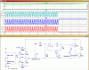
Hi everyone I have assembled this circuit http://www.ecircuitslab.com/2011/11/normally-chargers-available-in-market.html
**broken link removed**

and after many trials I got it to partially work, the problem is that, I can't get the relay to de energize
it's a 6v relay with coil resistance of 100 ohm (instead of the 250 ohm one in the original circuit), I can't find transistor SL100 so I tried 2n2222 it didn't work then I tried bc337 & whenever I connect the power to the circuit the relay energize & fast charging is taking place. the problem is the battery voltage rises up to 13.64 & the relay never de energize.
Vin to pin 2 of the UA741 is 6.87v & Vref is 6.43v, I removed both of the 100K resistors connected to Pin 2 & used a 220 K POT as a voltage
divider I thought if I made Vin lower than Vref I could get the relay to de energize but it didn't, I thought if it did work I would have to connect the +18v of X2 to the NO pin of the relay instead of NC so that when Vin is greater than Vref the relay energize & the float charging takes place.
here are a few things I noticed;
When Vin > Vref the output at pin 6 is -11.80v
When I make Vin < Vref the output at pin 6 is +13.40v
Vcc+ at pin 7 is +13.80v
Vcc- at pin 4 is -17.20v
if I remove transistor 1 (BC548) the relay still energizes
if I remove both transistors 1 & 2(BC548, BC337) the relay is de energized
I made the Lm324 voltage monitoring circuit on a separate PCB, along with the 3 100K resistors that are used to sample the battery voltage.
also I disconnected the the base of Transistor 5 (BC558) because when I connect the voltage monitoring circuit it causes the relay
to behave erratically.
I don't see the values of the opposing zener diodes clearly so I tried 2 8.2v diodes
& then 6.2v & 8.2 but it didn't seem to make any difference

I wish if you can help me to make the required changes if any to make the relay de energize when it should.
 
hi Max,
You say a 6V relay, surely it should be a 12Vdc relay.?
A 2N2222 is rated for 600mA continuous, so even with 100R load thats only 120mA.

E
 
With nothing connected to the base of T2 the relay should be de-energised. The fault can only be that T2 is connected incorrectly or has failed short circuit. Also as Eric says the relay should be 12 volt.

Les.
 
There is no current limiting resistor on the base of T2, so when T1 is on you'll probably blow the T2 transistor and it will then be short circuit.

I recommend putting a 1k resistor between T1 emitter and T2 base . And also putting a 10k resistor between the T2 base and T2 emitter to ensure T2 isn't turned on by any leakage current or cross coupling.

Also i agree with Eric, relay should be 12V.
 
Actually the 6V rating for the relay probably comes from the supply voltage minus the discharged battery voltage which may well be 6V. But you probably don't want your circuit to be damaged by a shorted or faulty battery so a 12V rating would be wise but i guess not strictly needed.
 
I have the same comment for T3 and T4, they need some base resistance.
In fact I can't see why T3 & 4 are being used, they seem to switch the 18V supply to the relay contacts only if the 18V is higher than the battery voltage. But the diode on the battery already prevents the battery from back energizing the transformer X2. So i can't see the point of this little bit of circuit.

This circuit seems to be a bit pants to be honest. I suggest you search our forum for a better battery charging circuit, I know we'll have one somewhere.
 
hi,
The output stage that is driving the relay effectively shorts out the +12V when T1 is ON.??
E
 

Attachments

  • A02.gif
    A02.gif
    52.6 KB · Views: 297
  • A04.gif
    A04.gif
    39.2 KB · Views: 299
There seem to be many things wrong or poorly designed with this circuit.

Half wave rectifiers
Smoothing capacitors too small I am thinking about C1 in particular.
What are ZD1 and ZD2 doing? I can only assume that it is to protect T1 and T2 from large reverse volts from the 741. A single 1N4001 could do this.
Voltage regulators augmented with diodes used as reference voltage sources. A simple zener would probably work just as well if not better.

As previously stated, the relay should have a 12v coil, and T2 is probably wired incorrectly or blown short circuit.

JimB
 
I agree with MisterBenn and Eric that the circuit is a poor design. I think the lack of base current limiting resistors and the fact that the transistors have a higher hfe value than the SL100 specified (SL100 min hfe 40) could have caused one or both of the transistors to fail. I think IC3, T3 and T4 are an attempt at a constant voltage charge when the relay is open. It should give 12 volts + 2 x red led forward voltage drops + 1 diode forward voltage drop - 2 x base emiter voltage drop = 12 +(2 x 1.8) + 0.7 - (2 x 0.7) = 14.9 volts. This is too high for a float charge voltage. There are also several other things I do not like about the design.

Les.
 
That Ecircuitslab website is full of errors and should be shutdown. Look at this one from there:
 

Attachments

  • bad sound to light circuit.png
    bad sound to light circuit.png
    142.1 KB · Views: 380
Note that the +/-12V supplies actually are +/-16V, something that will cause overheating in the relay coil. Also, the +18V supply actually is +24V ish.

Agree with all of the above, a poorly designed and overly complex circuit for the task.

ak
 
That Ecircuitslab website is full of errors and should be shutdown. Look at this one from there:

But it is such a nice professional-looking schematic - it must be a good design, it must! :nailbiting:
 
Thanks to God & Thank you so much everyone , I really can't thank you all enough

Les Jones indeed both BC548 & BC337 wiring weren't correct, for that purpose I used several parts of IC sockets to make the components that are likely to fail easily replaceable
I blown the few remaining BC548s & BC337s I had, despite the correct pin out.
I have seen SL100 used in many circuits online, & it's hard to find an equivalent that fits in directly.
I tired to measure the current drawn during charging, the Fast Charging mode the battery draw about 700 mA & the Float Charging mode it draw 300 mA
I used a small 12v 4Ah to test the circuit, but I plan to connect it to a car battery 12v 70Ah & I really have no idea how will it perform :confused:

Misterbenn Special thanks to you sir, your advice did the job :)I did exactly as you said & it finally worked you saved the last two BC548 & BC337 I had
now when I adjust the POT connected to pin 2 I can safely make the relay (energize - de energize) but I'm afraid that if I let that happen normally during charge, that the relay will behave erratically.
as I have mentioned that I made the voltage monitoring circuit on a separate PCB, I thought to add more functionality to it, so I connected a digital Panel Meter, it has 4 pins, I connected the +5V to the output of IC4 (
(I put a small switch to turn it off when not needed), ground to ground & the 4th pin to the Battery positive terminal, but sometimes when I turn the panel on it causes the relay to behave erratically by that I mean
switching on/off rapidly , switching the panel off/on solves that but I don't know exactly why ?!, could it be the negative terminal connected to Pin 4 of IC1 & Pin 11 of IC5 ?! or small current/voltage fluctuations drawn from IC4 disturbing the reference voltage of IC5 ?!
I do agree the circuit is far from perfect , as I don't have enough knowledge or experience so the circuit seemed pretty convincing to me.

ericgibbs that seemed to be the case before connecting the 10K & 1K resistors , thanks a lot for you efforts simulating the driver circuit

JimB I do agree, I really had no Idea but I have searched about those two opposing Zeners, & found out that they perform full wave clipping

audioguru thanks a lot for the useful information, I will never do it again, although I have learned a lot of interesting stuff while making this charger circuit.

AnalogKid
thanks a lot for your interest

gophert that's exactly what I have thought about it before going through all that pain.
 
Last edited:
Glad i was able to help.

could it be the negative terminal connected to Pin 4 of IC1 & Pin 11 of IC5 ?!

The pins you describe are actually -12V not ground so i hope its a typo!? If its not a typo then it may explain the odd behavior your seeing. I can imagine the meter having a over-voltage protection diode or similar on its input and this would then be trying to pull the -12V to 0V or pull the 5V to -7V. Whichever rail is stronger will win out but either way it wouldn't be good for your circuit or for the panel meter.

If that was a typo and you have actually connected it correctly then it may be that your drawing too much power from the 12V rail. All you regulators are pulling energy off the 12V rail and the extra loading your putting on IC4 may be pulling the 12V rail too low which would then effect the reference voltage for IC1. Although I expect that the 500mA supplied by T1 is more than enough, but you never know.

could you give us the part number of the panel meter your using?
 
Thank you so much really, I have connected it correctly, I didn't use the -12v to feed IC4.
Actually I used a 1A 12-0-12v for Transformer X1
could it be the length of the cable(30cm) ?! & that I didn't put a capacitor between the output & com legs of IC4
It's a Chinese 200V panel meter
I monitored the relay temperature it reaches 38-40 C when energized

Update: the relay chattering also occurs when Vin is close or equal to Vref

**broken link removed**

**broken link removed**


**broken link removed**
 
Last edited:
the relay is getting warm because its a 6V relay being powered by a 12V source. So you've got twice the design current going through the relay, it will work but may cause reliability issues in the future.

Can you clarify whats on either end of your 30cm cable. Is it the battery to circuit connection, battery to panel meter or transformer to circuit?

As you mentioned all the regulators will benefit from input and output capacitors.

The relay chattering is because of inadequate hysteresis or supply voltage variation.
 
From looking at the circuit your relay shouldn't oscillate. Assuming you've fitted the 1k resistor to T2 base I've calculated the turn on to be 6.36V and the turn off at 6.7V

Its important to note that before we put the 1K on the T2 base (so the circuit would work!) the turn off voltage was 6.42 (according to my very quick and basic calculation) so we've changed the switching point considerably which may be an issue. To fix this you could move the 1k to the T1 collector instead. I've put some images below to explain.
Original:
Capture1.jpg
Modified with 1K on T2 base
Capture2.jpg
modified with 1k on T1 collector, still protecting T2 base
Capture3.jpg

For completeness this is the circuit when V(-) > V(+)
Capture4.jpg

Note that the calculated values are very rough, the real values will depend on the parameters and tolerance of your components!

The oscillation you are seeing could be due to bad layout, noise pick-up & cross coupling or any number of reasons I'm afraid
 
Last edited:
Thank you so much & thanks to all who suggested a 12v relay, it's working fine now nearly no chattering at all with the digital panel meter disconnected.
also I guess that the changes I made to Vin by turning the 220K POT are fast, it's not the case during normal charging process, it might have contributed to the chattering.
your calculations are very close, but I guess I figured it out unfortunately the digital panel meter is based on ICL7107 from what I read about it, it needs isolated power supply
(although the panel works fine when the relay is in the "de energized" state)
I have put that to test & fed it 5v from an external power supply & it's true, it didn't cause any chattering as it did when it was connected to IC4
is there any way to get an isolated 5v from transformer X1 in the original circuit ?!
also I noticed that a 12v 4AH battery draws just 700 mA when the relay is energized is that normal ?!

here is what is on the other end it might be a bad layout
**broken link removed**
 
I noticed that a 12v 4AH battery draws just 700 mA when the relay is energized is that normal ?!
I would say not, if the battery is in good condition. But it depends on the battery chemistry. In theory that circuit will apply about 23V peak to the battery when the relay is energised !! Something is likely to get very hot :(.
 
Status
Not open for further replies.

Latest threads

New Articles From Microcontroller Tips

Back
Top