Continue to Site

Welcome to our site!

Electro Tech is an online community (with over 170,000 members) who enjoy talking about and building electronic circuits, projects and gadgets. To participate you need to register. Registration is free. Click here to register now.

  • Welcome to our site! Electro Tech is an online community (with over 170,000 members) who enjoy talking about and building electronic circuits, projects and gadgets. To participate you need to register. Registration is free. Click here to register now.

Can I make two inputs from one??

Jazz_3_4_5

New Member
Gents, & Ladies if that be the case....May I indulge my curiosity for a moment?

I have recently acquired a Japanese made Audio Mixer. that has seen some abuse. and as a learning experience,
I wish to bring it back into the fold for home use.

The Power supply is missing, and the Headphone Jack was smashed. I have found a replacement Headphone Jack, and will replace that when it arrives. In the meantime I have searched out the schematic, and this unit has a 3 legged power supply... two Positive legs and a Negative leg.

I am wondering if it is possible to use a 2 wire wall wart, and put a jumper in place of the second positive,
as shown in the schematic I included.
My thinking is that since the mixer, only draws 500mA maximum, a jumper should cover this situation.
Since I have no need for the Phantom power, as all my Mic's are Dynamic, & not Condenser types,
I'll disable it, by removing R101 A thru 104 A, and the 47 uF cap.

If you disagree with my diagnosis, please elaborate, and Possibly offer me an alternative.
I'm 80 yrs old, and trying to keep my mind as sharp as Possible, as I plan to keep using it
for at least another 30 years, and hopefully more!

You have my gratitude!


Question.jpg
 
If you've got the schematic, then post it - or at least post the make and model, so we can look it up.

As it is, your question is too vague, and possibly your assumptions are incorrect?. Generally in mixers they run off split supplies (for the opamps), so I would expect the three connections to be +18V, 0V and -18V.

However, the phantom power requires a higher voltage, so it 'could' be +18V, 0V, and +48V for the phantom power, if you post the full schematic we can tell you. I'm a bit dubious about it not having a split supply, though, and a single 18V supply sounds a bit on the low side (the +/-18V gives plenty of headroom).

However, as the phantom power is fairly low current, it 'could' generate that inside the mixer?.

I recently had to build a PSU for a medium size mixer, and that had a four pin socket for the PSU, +17V 0V, -17V, and +48V phantom power. As it was for gigging, we didn't need the phantom power, so I ignored that, bought two cheap Chinese 24V SMPSU's and modded them for 17V. It worked perfectly, and we did a gig a few weeks ago with it.
 
The "Plug AC Female" that you show your 18V DC adapter pointing to in your diagram is NOT where you need to input its supply, that must go in somewhere else (not shown)! The "Plug AC Female" is for a microphone input.
 
The "Plug AC Female" that you show your 18V DC adapter pointing to in your diagram is NOT where you need to input its supply, that must go in somewhere else (not shown)! The "Plug AC Female" is for a microphone input.

Well spotted, I presumed the schematic part was just to show the existence of Phantom power, it never occurred to me, he might be trying to plug power in there :D

Like I said above, he needed to post the schematic, or at least the make and model.
 
Hey all,
As you may have guessed I have no training in Electronics, except for
a course I took in college over 50 years ago that gave me the very basics,
in vacuum tube operations.
The reason I posted the"schematic" was to show removal of Phantom power.

I searched the internet for a schematic, and came up lacking
.I even emailed the company but got no reply
But if you care to repeat my search,
the brand name is Phonic,
model mm1202
that is all I have to go on.

the Phantom supply drawing is from a model mm1002,
and the only visible difference was the additional 2 inputs on the mm1202
and I guessed the 1202 followed the same game plan.
as I found no model 1102


If I can't find a solution within my means,
I'll probably place it on eBay, for parts.

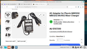
I got the voltages and current from a replacement power supply, for which they wanted $107.00 plus shipping from Australia...to USA, a price I deemed to be far beyond my fixed income, and desire to spend
...hence the question posed.
 

Attachments

  • Screenshot from 2025-06-17 09-21-12.png
    Screenshot from 2025-06-17 09-21-12.png
    432.7 KB · Views: 10
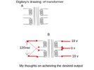
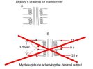
Right - the manual (for the MM1002) clearly shows the PSU on page 12 - the external PSU is simply a mains transformer, and provides 18-0-18 AC via the power supply socket (next to the power switch).

This MUST be AC, and 18-0-18, it can't be anything else, or any leads joined together.

However, 18-0-18 is a standard mains transformer, and freely available - buy one, stick it in a suitable box, run a mains lead to the primary, and a three core lead from the secondary to a suitable plug to fit the mixer.

The only difficulty will be finding a suitable plug - and the manual confusingly calls it a 'BNC jack', and only shows a made up drawing of it. The mixer I did used what looked like a CB/Aviation microphone plug - and we managed to get a suitable on our second try. The first one was too small, we didn't know they did different sizes? - the second one (from the same company) fitted perfectly.

However, the Phonic one looks a little similar to a DIN plug?.
 
If I read the picture of the power adapter correct, it shows output (OP) as AC voltage, not DC.
That makes sense if there is rectification farther in the schematic.
 
YES !!! Thank you so much!!
I have the original plug, which has a ring to screw the plug to the receptacle.
When it received it's last trauma the plug was attached to the unit, and it left
about 12mm of wire with it. I have already disassembled it and was waiting
to proceed until I could learn more about it. Yes I remember the CB plug,
from my CITIZENS BAND days, in the early 60's.. My handle back then
was "The Lollipop Kid". ha ha!

Again, many thanks for your (collective) time.

I'll check out your website too , a little later, your PIC for beginners,
looks like something I might put to good use as I'm doing some experimenting ,
with Arduinos.

Charlie
aka Jazz
If I read the picture of the power adapter correct, it shows output (OP) as AC voltage, not DC.
That makes sense if there is rectification farther in the schematic.
Yes you are correct it needs to be AC current. as Nigel Goodwin wrote.
 
YES !!! Thank you so much!!
I have the original plug, which has a ring to screw the plug to the receptacle.
When it received it's last trauma the plug was attached to the unit, and it left
about 12mm of wire with it. I have already disassembled it and was waiting
to proceed until I could learn more about it. Yes I remember the CB plug,
from my CITIZENS BAND days, in the early 60's.. My handle back then
was "The Lollipop Kid". ha ha!

Again, many thanks for your (collective) time.

I'll check out your website too , a little later, your PIC for beginners,
looks like something I might put to good use as I'm doing some experimenting ,
with Arduinos.

Charlie
aka Jazz

Yes you are correct it needs to be AC current. as Nigel Goodwin wrote.
Also to note the reason why there can't be any wires joined together, is because the transformers centertap makes the two positive ends out of phase with each other.... Correct?

Charlie
aka Jazz
 
Also to note the reason why there can't be any wires joined together, is because the transformers centertap makes the two positive ends out of phase with each other.... Correct?

Charlie
aka Jazz
Yes, you need a spilt supply, made possible by the tap (while it looks like a bridge, it's actually two full wave rectifiers), and you're wanting 36V as well, in order to create the 48V Phantom power.
 

Latest threads

New Articles From Microcontroller Tips

Back
Top