Jazz_3_4_5
New Member
Gents, & Ladies if that be the case....May I indulge my curiosity for a moment?
I have recently acquired a Japanese made Audio Mixer. that has seen some abuse. and as a learning experience,
I wish to bring it back into the fold for home use.
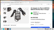
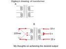
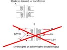
The Power supply is missing, and the Headphone Jack was smashed. I have found a replacement Headphone Jack, and will replace that when it arrives. In the meantime I have searched out the schematic, and this unit has a 3 legged power supply... two Positive legs and a Negative leg.
I am wondering if it is possible to use a 2 wire wall wart, and put a jumper in place of the second positive,
as shown in the schematic I included.
My thinking is that since the mixer, only draws 500mA maximum, a jumper should cover this situation.
Since I have no need for the Phantom power, as all my Mic's are Dynamic, & not Condenser types,
I'll disable it, by removing R101 A thru 104 A, and the 47 uF cap.
If you disagree with my diagnosis, please elaborate, and Possibly offer me an alternative.
I'm 80 yrs old, and trying to keep my mind as sharp as Possible, as I plan to keep using it
for at least another 30 years, and hopefully more!
You have my gratitude!

I have recently acquired a Japanese made Audio Mixer. that has seen some abuse. and as a learning experience,
I wish to bring it back into the fold for home use.
The Power supply is missing, and the Headphone Jack was smashed. I have found a replacement Headphone Jack, and will replace that when it arrives. In the meantime I have searched out the schematic, and this unit has a 3 legged power supply... two Positive legs and a Negative leg.
I am wondering if it is possible to use a 2 wire wall wart, and put a jumper in place of the second positive,
as shown in the schematic I included.
My thinking is that since the mixer, only draws 500mA maximum, a jumper should cover this situation.
Since I have no need for the Phantom power, as all my Mic's are Dynamic, & not Condenser types,
I'll disable it, by removing R101 A thru 104 A, and the 47 uF cap.
If you disagree with my diagnosis, please elaborate, and Possibly offer me an alternative.
I'm 80 yrs old, and trying to keep my mind as sharp as Possible, as I plan to keep using it
for at least another 30 years, and hopefully more!
You have my gratitude!

 BTW, my father was a Brit...from somewhere in Manchester.