Electro Tech is an online community (with over 170,000 members) who enjoy talking about and building electronic circuits, projects and gadgets. To participate you need to register. Registration is free. Click here to register now.
Welcome to our site! Electro Tech is an online community (with over 170,000 members) who enjoy talking about and building electronic circuits, projects and gadgets. To participate you need to register. Registration is free. Click here to register now.
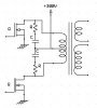
Please find attached file and help me to calculate the value of capacitor & Resistor for R-C Snubber. For the frequencies of 20KHz & 50KHz. Please also provided a simple formula.
1. THe capacitor should be much greater than the capacitance of the MOSFET to properly dampen the oscillations and absorb the voltage spike (the specific capacitance is the one which the parasitic inductance will oscillate). As the capacitance gets bigger your have less overshoot but you also dissipate more power in the resistor and there are diminishing returns for larger and larger capacitors. The optimal value where the diminishing returns starts to really kick in and the power dissipation starts to increase too much for what you get is around 2,3,4x the MOSFET capacitance.
So just pick a capacitor value based on what I said above (there are ways to optimize but...yeah you need to actually measure and know the inductances in the circuit etc).
2. THe resistor's purpose is to stop the transistor from burning out when the capacitor discharges it's stored energy when the transistor switches on by limiting the capacitor's discharge current. So it is preferably it is as low as possible so that it interferes as little as possible with the capacitor's absorbing of the spike (the inrush current through the resistor will cause the voltage spike to be higher).
So use R=VI where I is the operating current and V is the maximum voltage spike you can tolerate.
3. To figure out the resistor power rating you need use:
P = fCV^2
And of course, make sure you use resistors and capacitors with minimal inductance and that the capacitor can handle the current spikes or dv/dt (depending on the manufacturer's datasheet). This is just two different ways to rate basically the same thing since I = C*dv/dt and you can jump back and forth between the two.
Sorry half of everything I know about snubbers is in that one document. THe other half is in one other article. I'm just an end-user of snubber circuits. I didn't even notice that the article even had an author! Let alone that he wrote books. What's the name of the book?
Please find attached file and help me to calculate the value of capacitor & Resistor for R-C Snubber. For the frequencies of 20KHz & 50KHz. Please also provided a simple formula.
When we would set up snubbers, you pick the cap value based on power dissipation given by P = CV (squared) F. In general, you need to use a non-inductive metal oxide or carbon comp resistor to prevent RFI ringing. These resistors come in 1W, 2W, and 3W ratings. Non inductive wirewound resistors exist but are pricey and do radiate some EMI. Metal oxide are better for snubbers. Stack in series if more power is needed.
The snubbers burn the same power regardless of load current, so you want to minimize it. In general, you don't want to burn more than about 3- 5% of MAXIMUM rated converter power in the snubbers. So, for a 100W converter, keep it under 5W.
Capacitor type: for your app, you will probably use high voltage ceramic discs. There are high voltage poly caps but they are prone to peak current failure. Ceramic discs are more durable.
As for the resistor Ohmic value: to some degree this is selected based on empirical experiment on the prototype because you are tuning out a transformer/system resonance and trying to minimize ringing. BUT: note that when the converter switches, there is a peak current which is the switch voltage (across the snubber) divided by the resistor so don't go too low in resistance. In general, the peak snub current shouldn't be more than about 20% of the peak switch current of the FET switch because this added peak current has to be delivered by the FET.
This site uses cookies to help personalise content, tailor your experience and to keep you logged in if you register.
By continuing to use this site, you are consenting to our use of cookies.