Continue to Site

Welcome to our site!

Electro Tech is an online community (with over 170,000 members) who enjoy talking about and building electronic circuits, projects and gadgets. To participate you need to register. Registration is free. Click here to register now.

  • Welcome to our site! Electro Tech is an online community (with over 170,000 members) who enjoy talking about and building electronic circuits, projects and gadgets. To participate you need to register. Registration is free. Click here to register now.

Building a Rechargeable LED Lamp

Status
Not open for further replies.

Connollacken

New Member
Hello Sparkies of the Internet,

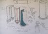
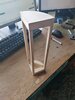
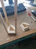
I am just a simple man of wood, with absolutely no experience in anything electric. I am however building a lamp for a project that I am doing as part of my course in Furniture Design and Manufacture, and I fear that I have made it slightly too complicated for the amount of time that we have to actually complete the project. My lamp consists of 4 separate wedges with their own strip of LEDs, each a quadrant of a cylinder. They connect together to make the cylinder. I want them to be able to turn on without having to be connected, but I would also like it so that just one of the quadrants has a USB charge input, and that they only charge once they're all connected using magnets (which I'm wondering if the current could pass through?). Oh and the lamp is also flat packable, so the LED strip and battery will be attached to separate components.

First question is: Will this be possible?

They'll obviously all need separate batteries, but what kind of batteries should I be looking for? Lithium-ion?

I can upload photos of the concept, if there's anyone willing to help. Of which is hugely needed.

Thanks in advance
Sean
 
So there is an example of one of the quadrants. Each one has a sort of cap on either end which hinge them open (as in, going from flat to a right angle). The LED strip will be attached to the bar at the right angle of the wedge.
 

Attachments

  • For Forum.jpg
    For Forum.jpg
    1.1 MB · Views: 268
  • IMG_20201110_121340.jpg
    IMG_20201110_121340.jpg
    2.7 MB · Views: 267
  • IMG_20201110_121420.jpg
    IMG_20201110_121420.jpg
    3.3 MB · Views: 249
My suggestion would be to use power banks for the batteries. They give a regulated 5 V output, and a simple resistor in series with each LED is all that's needed to control the current.

It's not the most efficient, but it only needs a minimum of components, and charging can be done from any USB connector.
 
It's quite a small piece. The power bank would be too clunky and heavy no? I'd also have to have 4 of them, which definitely isn't efficient. As it's a college project, that's the kind of thing that'd be scrutinized
 
You could probably get the magnets to double as connectors, which would allow you to have just one battery.

What is the specification of the LED strip? How long do you need the LEDs to be alight for? How are you intending to turn it off and on? Do you need a rechargeable battery? If you're only going to use it a few times, replacing non-rechargeable batteries are cheaper.
 
The full LED strip is 12 volt, but I'm gonna cut the 5 metres that I'm buying into about 26cm strips. Will that affect the amount of volts needed? I want the quadrants to each turn on without having to connect all of them, so they'll definitely all need batteries.
What about using LiPo batteries in each? I might have to run them through a small converter to get them up to 12v, would I? I could then possibly charge the batteries using a wireless.
I'd like the LEDs to be alight for as long as they're on. The aim is to make a lamp that will be rechargeable. The turning on and off of the lamp, I don't know anything about yet. Any ideas?
 
Assuming you bought the strip with 60 LEDs/M then it takes ~5W per meter, a 26cm strip (I think you'll have to cut at the 25cm mark) will take about 1.25W. A small LiPo battery has ~7W available and will light 1 short strip for about 4 hours. The advantage of the linked battery is it'll probably fit in the base. Note, you need a special charger for LiPo batteries. Also, if you add strips the battery time will shorten - 4 strips = 1 hour.

Mike.
Edit, shorter strips still need 12V - it's the current that is reduced. So you'll need a boost circuit as well.
 
Thank you. Yea I was thinking to have a battery and now a booster on each quadrant. (May have to make it bigger). I see that I might have another problem with making a wireless LiPo charger. Seems possible though?
 
When your job is finished, please upload a picture, so that next time we encounter making a rechargeable LED light, we have experience.
 
For each wedge, you could have:
  • To boost from 3.7V battery to 12V: **broken link removed**
  • For the switch, you could use a touch switch, configured for toggle mode: **broken link removed** The output of this switch can connect to pin 4 (MT3608 enable pin) of the IC on the boost converter.
  • To charge and protect the battery: https://www.ebay.com.au/itm/164271308971
The main wedge is the same as the others, except it has the charging socket exposed.

The 5V from the charger can be passed through the magnets, provided you're using those with a conductive coating, i.e. Ni coated neodymium types.

If you want to have charging only enabled when all four are connected together, you could have three loops (via the magnets) around assembled lamp, where one loop is the 0V connection, one is 5V in, and one is 5V charge. The 5V and 5V charge loops are connected in the main wedge, such that the 5V in is only connected to the 5V charge loop when all wedges are connected.
 
Thank you. Yea I was thinking to have a battery and now a booster on each quadrant. (May have to make it bigger). I see that I might have another problem with making a wireless LiPo charger. Seems possible though?
If you make the top (or bottom - more stable) part hollow it will house the battery, charger and boost circuit. I would avoid wireless charging as that presents a whole new problem.

Mike.
Edit, the battery I linked to earlier has built in protection.
 
Last edited:
Unbelievable stuff, thanks everyone. I'll credit ye when I've made millions haha. Next question though, and it could be the simplest of all, am I using awg jumper wires to connect these various components, or what's the best way to do that?
 
Soldering to a magnet is very difficult or impossible. I suggest conductive glue or some sort of clamp. You could probably solder to a steel object and let the magnet attract that to the back face of the magnet.
 
They're fairly small, so not really. The conductive glue might be the best option?
I'm still not 100% on the wire situation, ie. what to use
 
The wire isn't critical. Any size of wire that you can handle, strip the insulation from and solder will be adequate for this application.

When you have high currents, high voltages, signals that might be affected by noise, long runs of wire, high temperatures, need of waterproofing or other specialist requirements, you need special wires. Here, anything will do.
 
Status
Not open for further replies.

Latest threads

New Articles From Microcontroller Tips

Back
Top