amanmazleigh
New Member
Hello guys!
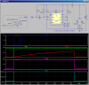
I am trying to build a circuit and had been thinking about it for a few days but came out with no solutions. I am trying to build a circuit of which when a button is pushed, the 555 timer which is to be configured as a one shot multivibrator will send out an output for 3 seconds. This output will then be sent into a solid state relay which then will close the internal switch. An 18 V supply will then flow through the closed circuit to power the solenoid until after 3 seconds. After three seconds, the one shot multivibrator will go back to its low output state.
I've tried simulating it in MultiSim but the results I got are very erratic. I'm not sure if its my fault or just the simulations fault.
Details of the circuits that I intend to use is as follows though if you guys think it should be modified by all means you can tell me that.
Supply voltage to 555 timer: 9V battery voltage regulated to 5V
Supply to solenoid: 18V (2 9V batteries connected in series)
Voltage regulator: National Semiconductor LM7805CT
555 timer model: National Semiconductor LM555CN
Solid state relay: Vishay Semiconductor LH1500AT
I am intending to use a microswitch for the timer's trigger input.
I am not sure if I should use solid state regulators ot the normal relays. I've heard that solid state relays are more reliable. Please advice me on that too.
I can provide the MultiSim drawing that I did if requested. I really appreciate the help given.
With regards,
Aman.