Continue to Site

Welcome to our site!

Electro Tech is an online community (with over 170,000 members) who enjoy talking about and building electronic circuits, projects and gadgets. To participate you need to register. Registration is free. Click here to register now.

  • Welcome to our site! Electro Tech is an online community (with over 170,000 members) who enjoy talking about and building electronic circuits, projects and gadgets. To participate you need to register. Registration is free. Click here to register now.

buffer for oscillator circuit

Status
Not open for further replies.

pc88

New Member
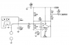
I've built this oscillator for determine the resonance of LC tanks:

https://www.qsl.net/iz7ath/web/02_brew/21_LCMeter01/fig/fig08.gif

except that I didn't implement the NAND gate buffer. Instead I'm trying to use just a 2n7000 N-FET (common source configuration with a 10K drain pull-up). The problem is that I'm seeing substantial glitches (~ .5 V) on the up transitions and the rise time is now very noticable. The high-to-low transitions are fine.

I'd like to square up the output signal as much as possible without using another CMOS IC. Any suggestions? Should I use a different transistor? smaller pull-up? add a cap somewhere?

For reference, here's the associated article for the schematic:

https://www.qsl.net/iz7ath/web/02_brew/21_LCMeter01/
 
Last edited:
Use a 15V supply so the 4011 will be very fast.
Connect the output capacitor C6 to the output of U2b.
 
audioguru said:
Use a 15V supply so the 4011 will be very fast.
Connect the output capacitor C6 to the output of U2b.

Thanks for the pointers, but I'm not using the 4011. I've replaced it with a 2n7000, and I'm getting about .5 V overshoot on the up-transitions (but no ringing). Also, FWIW, I'm using a 5V supply. I'd like not to resort to a 14-pin IC, although any CMOS Schmitt trigger gate would work very well.

I've change it to a source follower, and I'm getting a much cleaner signal, although it's only 2.5V signal instead of a 4.5V signal. Still, I'd like to understand the issues around the original circuit. I'm pretty sure the overshoot is causing extra counts to be registered by my frequency counter.
 
The pullup resistor on the LM311 is 1k so that is about as good as it will get without having a push-pull IC like a logic inverter.
 
Use an 8-pin low voltage (i.e., not 741) op-amp with fairly high gain? :)

Not sure why you don't want the 4011, frequency too low or something against CMOS ICs?
 
audioguru said:
The pullup resistor on the LM311 is 1k so that is about as good as it will get without having a push-pull IC like a logic inverter.

okay - thanks... now I can stop pulling my hair out :)

boxer4 - nothing against the 4011, expect that in this case I don't want to use that much real estate.
 
Use an SMT 4011 if you haven't got enough room for the through hole DIP.
 
I thought of that but you need four NANDs not one.
 
Do you think so? I know the schematic calls for four, but they are just chained together presumably only to make sure their inputs aren't floating.

The use of R6 is a little puzzling, and I can't think of a good reason for it.
 
pc88 said:
Do you think so? I know the schematic calls for four, but they are just chained together presumably only to make sure their inputs aren't floating.

The use of R6 is a little puzzling, and I can't think of a good reason for it.
I agree, a single gate IC is probably an ideal solution.
 
blueroomelectronics said:
I've seen that LC oscillator before, used a PIC as an LC meter. What are you connecting it to?

On the input side I'm connecting it to various LC tanks I'm toying with, the present one being an antenna for lightning detection and direction determination. On the output side I'm just connecting it to a frequency counter.
 
pc88 said:
On the input side I'm connecting it to various LC tanks I'm toying with, the present one being an antenna for lightning detection and direction determination. On the output side I'm just connecting it to a frequency counter.
If your counter is sensitive, as most are, just add an attenuator to isolate the counter loading from the LM311 output, as below.
 

Attachments

  • LC osc.PNG
    LC osc.PNG
    14.3 KB · Views: 1,476
Status
Not open for further replies.

Latest threads

New Articles From Microcontroller Tips

Back
Top