Continue to Site

Welcome to our site!

Electro Tech is an online community (with over 170,000 members) who enjoy talking about and building electronic circuits, projects and gadgets. To participate you need to register. Registration is free. Click here to register now.

  • Welcome to our site! Electro Tech is an online community (with over 170,000 members) who enjoy talking about and building electronic circuits, projects and gadgets. To participate you need to register. Registration is free. Click here to register now.

Broken wire detection

Status
Not open for further replies.

Boncuk

New Member
Hi everybody,

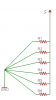
I want to make a HV-wire on top of a fence. The HV is fed through the entire cable length. To find the location of the broken wire easily between two poles of the fence I want to divide that wire into may sections.

My idea: Connect a constant current source (4mA) to each section (between two poles) and measure the voltage drop in the controller at the load resistor having 500Ohms. As soon as one section is broken the voltage drop (normally 2V) reduces to zero and trigger the alarm circuit indicating the exact position of the damage.

Both circuits will have separate ground connections, the fence will have "earth" as ground.

Could that circuit work OK?

Boncuk
 
Last edited:
I think the idea as you have described it is nonsense. How can you have a high voltage conductor with sections having a current source in parallel with a section of the conductor. You'd better draw this one up in case I've missed something.
 
Broken wire detetection

:confused:
Papabravo said:
I think the idea as you have described it is nonsense.

Hi Papabravo,

so far so good. The problem is easy to understand. You can have two different signals on one wire if you use different ground connections for each.

Drawing two poles and a wire in between will not cause you to understand anything, even if I draw the two circuits in it.

On the other hand I expected to join a forum where persons are respected as persons. That isn't quite the case according to your disqualifying post. From my profession I had to use the word "nonsense" with special care.

If I had used it a careless way I bet there would have been an outcome of at least 40% less pilots than there are in Germany.

So please be so kind as to watch your choice of words in the future.

Kind regards

Boncuk (also known as Herman the German)
 
hi,
How many different sections will there be in the fence? How long is each section??

The current loop in each section would be easy to do, I think powering each current section with its own power supply could be a problem from the point of isolation from the high voltage main fence.

How do you plan to power the individual current loops?
 
Boncuk said:
:confused:

Hi Papabravo,

so far so good. The problem is easy to understand. You can have two different signals on one wire if you use different ground connections for each.

Drawing two poles and a wire in between will not cause you to understand anything, even if I draw the two circuits in it.

On the other hand I expected to join a forum where persons are respected as persons. That isn't quite the case according to your disqualifying post. From my profession I had to use the word "nonsense" with special care.

If I had used it a careless way I bet there would have been an outcome of at least 40% less pilots than there are in Germany.

So please be so kind as to watch your choice of words in the future.

Kind regards

Boncuk (also known as Herman the German)
Sir,
It is possible to atack an idea or a statement of an idea without attacking the person. There was no personal attack or disrespect in my post. I do not choose my words in a careless fashion. I stated quite simply my observation on the idea as described. If you care to clarify what you are doing and why; more help may be forthcoming. As always a picture or diagram is worth at least 1,000 words.
 
Broken wire detetection

Hi both of you, Papabravo and Eric,

I have changed my plan a little bit thinking about high voltage isolation between the two circuits.

Here are some details: A timer circuit around an TLC555 produces pulses of variable lengths of 16.5, 24 and 31ms which results in 250, 400 and 450mJ of power respectively applying an ignition coil used in ectronic ignition devices for cars. (I just preferred a TLC555 to an NE555 because of the high value timing capacitor of 1.5uF) to keep the pulse repetition down to 1.5 seconds.

(That device is not meant to electrocute any person or animal)

Using inductive couplers there could be a broken segment which will not be detetcted because another one might be broken too.

Burglary is some kind of common business in Thailand and living on the country side it is quite easy to empty entire houses if nobody is present.

The fence consists of a total of approximately 50 segments which I want to check individually.

Now taking into consideration, that there is a break of almost 1.5 seconds between HV pulses I could use constant current loops for each segment to be powered when there is no high voltage on the wire.

Instead of using a loop of 4mA I could also use 20mA which result in a voltage drop of 10V with a burden of 500Ohms.

Regards

Boncuk
 
Last edited:
I see what you have in mind. When there is no HV present the current loop can be successful in detecting a broken wire. When HV is present you need to control any and all leakage currents. The placement of the isolation components will be critical. If they are anywhere except at the posts the current loop wires will have HV on them and corona discharge to nearby items, animals, and people is a real possibility. Each segment appears to need two isolation components for a total of 98. 50 posts is 49 segments after all. You would not have to test each segment between HV pulses you could do it in random order a couple at a time.

I still think the idea is impractical and that there are better solutions from both a technical and a security perspective. Not to mention cost.
 
Here's a real wild hair. An NE-2 neon bulb will light when placed next to a spark plug wire in a car, so it should work here. If the NE-2 quits firing, the wire is broken upstream. Couple this to a phototransistor. You now have an indicator with built-in high voltage isolation. Of course, you can't test when the HV is off. Don't know if this is a problem or not.
 
Broken wire detetection

Hi Papabravo and Ron,

I guess there is another way too to detect a section of a broken wire. However I don't have a better idea for the time being. There will be discharge only if anything or anybody touches the wire which is connected to earth on the ground connection terminal of the ignition coil. Using a power supply isolated from mains it would have a different ground connection. As an additional safety feature I could use relays to totally disconnect the current sources as soon as the ignition coil is activated.

The cost will be moderate compared with those of a new household every once in a while.

Using Neon lamps is certainly a good idea. Using 50 of them will require higher power than the ignition coil is able to deliver. A short electric shock of a maximum of 450mJ will not harm anybody, but give a distinctive signal to keep out.

Of course I could use just one Neon lamp and fire heavy machine guns as soon as the wire is broken. :D But it would be beyond my budget, replacing the entire fence for a broken wire. :rolleyes:

Hans
 
here's my idea, untitled.PNG ,if the wire is cut the total resistance will change,the current will change too. you need current detector
that produce alarm signal when the current is change.
 
Broken wire detetection

Hi jumides,

that doesn't solve my problem. I want the entire wire divided into many sections to be able to tell the exact position of the interruption.

Also keep in mind: I was talking about HV (high voltage of approximately 15 to 20KV)

Nevertheless, thanks for your idea.

Boncuk
 
Boncuk said:
Hi Papabravo and Ron,

I guess there is another way too to detect a section of a broken wire. However I don't have a better idea for the time being. There will be discharge only if anything or anybody touches the wire which is connected to earth on the ground connection terminal of the ignition coil. Using a power supply isolated from mains it would have a different ground connection. As an additional safety feature I could use relays to totally disconnect the current sources as soon as the ignition coil is activated.

The cost will be moderate compared with those of a new household every once in a while.

Using Neon lamps is certainly a good idea. Using 50 of them will require higher power than the ignition coil is able to deliver. A short electric shock of a maximum of 450mJ will not harm anybody, but give a distinctive signal to keep out.

Of course I could use just one Neon lamp and fire heavy machine guns as soon as the wire is broken. :D But it would be beyond my budget, replacing the entire fence for a broken wire. :rolleyes:

Hans
You may not know that the neon lamp doesn't require a physical connection to the HV wire. The voltage gradient near the wire is enough to ionize the gas inside. I suppose this does impose some small load on the HV source, but I don't know how much.
You don't need the lamp to be continuously lit. It would be simple to make a missing pulse detector with something like a retriggerable oneshot (monostable multivibrator).
 
Here is another idea. Put opto coupler input in the ground side of the loop. Monitor the output of the opto coupler, if the input current stops the output will also stop.
 
Broken wire detetection

Hi Ron,

I certainly know that a neon lamp doesn't require a physical connection to the "transmitting" line, but a descent ground line - at least somebody holding the lamp. I tried that out as radio amateur using an incandescent lamp. The lamp changed its brightness with the modulated signal. However the effective transmitting range was reduced drastically.

RIAS Berlin wondered about their reduced range of a commercial short wave transmitting station some time ago. The reason was stealing of RF-energy to illuminate gardens. 1000 light bulbs connected to coils of two or three windings did the job.

Also cutting the line somewhere in the entire loop will cause all the follow-on neon lamps to extinguish, meaning in the worst case, cutting the cable at the feed line will not indicate anything but a general failure.

I know from high security military installations (e.g. nuclear weapon depots) that the fences there will fry intruders (dual, the inner charged). If somebody manages to cut the cable an alarm will be triggered pointing to the exact position of the damaged cable.

Using either inductive, optoelectronic or capacitive sensors there is just one disadvantage to all of them. A cut wire won't indicate the position.

Ron, if you come up with an idea which solves the problem to my satisfaction, I'll invite you to Thailand and you'll be the first to "P" onto the wire. :D
 
Last edited:
Boncuk, you said,
Also cutting the line somewhere in the entire loop will cause all the follow-on neon lamps to extinguish, meaning in the worst case, cutting the cable at the feed line will not indicate anything but a general failure.
Does this mean you expect an intruder to cut the fence in multiple places simultaneously, in an attempt to defeat your detection system? If they only cut it in one place, it won't matter that the downstream lamps are extinguished.
BTW, 250mJ in 16.5mS is 15 watts peak power, isn't it? 50 NE-2's at 15mW apiece is 750mW. Did I make an error in my calculations?
 
Broken wire detetection

Hi Ron,

thieves are normally smart. They spy their objects for weeks sometimes to make sure they can do their "work" without any disturbance. If they find any alarm device they will of course cut a simple wire at several places just to take no risk.

First thing which will be kind of hard for them is the quality of the wire. It will be stainless steel of 6mm diameter. In order to cut that they will have to use a bolt cutter which is normally not isolated.

I really don't care shooting a burglar in my garden. But getting out in the dark and search for somebody around I prefer to blind fire onto the given location.

In the meanwhile I have worked out a schematic for just one section. It will take a lot of relays but that doesn't bother me as long as the desired function is achieved.

ST offers a current sensor which works with two different voltages. The high side can use up 30V input voltage and the low side can be supplied by any MCU power supply. The current it consumes is comparatively
very low at 300µA.

Have a look at the design and post your opinion please.

Thanks

Hans
 
Broken wire detetection

Sorry,

upload failed, here it is

**broken link removed**
 
Let me just throw out another idea. It could detect and locate two cuts easily, but not more. Of course, the plan you have to monitor each segment could detect more cuts, but might be more complicated.

Someone earlier suggested a resistence network, such as shown below. The wire could be connected to ground at many places and from the total resistance to ground at the source, one could calculate which segment was cut.

What if instead of resistance, one looked at capacitance, and instead of using ground as the reference, simply used a twisted pair? In other words, the uninsulated live wire would be twisted with an insulated wire.

As an experiment, I took a partially used roll of telephone (CAT 3) wire. It was initially 250 ft, but I had used quite a bit of it. The capacitance between one pair was 2.16 nF. I removed 8 ft and the resulting capacitance was 2.00 nF (i.e., 0.02 nF per foot). That would allow me to estimate the remaining length at about 100 ft, which is about what it looks like.


In practice, if the current to the hot wire drops (or any other factor you may monitor) indicating a cut, one could immediately measure capacitaance from each end and determine the location of the cut or cuts in distance from the source. Of course, the capacitance measurement could be made by a variety of means; I simply used a meter for this experiment. If the high voltage is pulsed, you could get a measure of it continuously. John
 

Attachments

  • network.png
    network.png
    8.6 KB · Views: 340
hi boncuk,
Its unusual for the intruder to cut the HV wire on the electric fence.
In South Africa, a common way is just to throw a grounding wire over the HV wire or a wet blanket/carpet.

If you dont test for a grounding link then you will not be aware the fence is grounded and its useless.

Roff's idea of detecting the presence/or lack of the HV pulse is the best way.

Is the HV fence wire a continous loop.?
 
Broken wire detetection

Hi to all involved in the problem,

the entire HV part has been taken care of already. There is no way to ground the HV without detection. I just didn't mention that because it is the most simple part of the installation. It is done by measuring the voltage drop over a defined terminating resistor between the hot line and earth.

Measuring the capacitance in a twisted pair of wires burries too many 'perhaps' and estimation work. Measuring the current flow through each segment during HV pulse pauses is from my sight, the most promising solution. This kind of measurement just requires a minimum voltage drop of 910mV to indicate the segment is OK. All higher voltages will indicate an OK-status too.

If the minimum voltage drop is not present there is definitely something wrong with the fence.

I know that it takes a lot of circuitry, but as I already mentioned will the investment by far not exceed the cost for a completely new household now and then, not to speak about items which will not replaceable like personal and unique belongings.

Regards

Hans

P.S. A timing diagram is already contained in my faulty schematic. Correction to follow.
 
Status
Not open for further replies.

Latest threads

New Articles From Microcontroller Tips

Back
Top