Continue to Site

Welcome to our site!

Electro Tech is an online community (with over 170,000 members) who enjoy talking about and building electronic circuits, projects and gadgets. To participate you need to register. Registration is free. Click here to register now.

  • Welcome to our site! Electro Tech is an online community (with over 170,000 members) who enjoy talking about and building electronic circuits, projects and gadgets. To participate you need to register. Registration is free. Click here to register now.

Breath Controller with 3.5mm Jack to make 0 - 5 V Variable voltage (Control Voltage) on 6.5mm Jack

Status
Not open for further replies.

Nicholas D

New Member
I am a beginner and wish to tackle this project...

I have an old Yamaha breath controller device that has a 3.5mm Jack and requires -9v on the tip (the sleeve is positive). It draws a current of approx 7mA to 20mA depending on how hard you blow it (from what I have managed to research but may be wrong). I want to now reimplement this device to control CV (control voltage) on my synthesizer. I would love some help to know how to achieve this... I was thinking to use a 9v battery to power it, then convert the voltage to a variable 0 to 5v so that I can plug it into my Sythesizer CV input (6.5mm Jack) and vary the voltage by blowing... Will a simple resistor in circuit achieve this? How would you go about it?

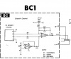
Attached is the circuit diagram of the Breath Controller in case it helps ;)

Thanks very much!
:joyful:
Nicholas
 

Attachments

  • BreathControllerCircuitDiagram.png
    BreathControllerCircuitDiagram.png
    101.5 KB · Views: 345
Welcome to ETO, Nicholas D!

Found this site, with **broken link removed**. Not sure if it's useful. Couldn't find what, exactly, the BC2's output voltages are, although from the schematic I came make a SWAG.

Do you know what the output value(s)?

Might be as simple as using a simple voltage divider circuit at the output of the BC2 to derive a voltage range suitable for your synth.

<EDIT> Just found this:
"BC INPUT
The BC input on the Kurzweil K2661 is compatible with Yamaha BC1, BC2, and BC3. It is a 3.5mm stereo jack that: provides -15.32 V on tip, expects a range of -0.5V to -8.5V from BC on ring, sleeve is ground. The suggested maximum current load for the BC input is 20mA..."

From this site.

So a voltage divider circuit sounds good, anyway...
 
Last edited:
Fleshing out the voltage divider idea ......
BC-to-Synth.PNG
 
Thanks, alec! That's what I had in mind (just didn't SIM it out... :banghead:).
 
That's really awesome of you guys, thanks so much... I can easily rig it up and try it out with a voltmeter first and see if I get 0 to 5v on the output :)

alec_t - really helpful thanks.... please forgive my ignorance... So this circuit is showing 2 x 9v batteries in series... Also is this using the formula?:

Vout = Vin x (R2 / (R1 + R2))

Because with this I calculated that a 10k and an 8k resistor would yield a Vout of 5v, given 9v Vin. So just curious how you calculated 11k for R2.

e.g. 5 = 9 x (10 / R1 + 10), R1 = 8k

Wouldn't Vout equal more like 4.3V? Vout = 9 x (10 / (10 + 11)) = 4.3?

I did some research but yeah have really minimal knowledge so really appreciate as much info as possible here... Love to learn.

Thanks again!
 
So this circuit is showing 2 x 9v batteries in series..
Yes. V1 provides +9V to the top of R1 and V2 provides -9V to the jack tip of the BC.
I didn't use any formula: I left that to LTspice :).
The sim assumes the output voltage from the BC varies from 0V to -9V (your mileage may vary).
With R1=10k and R2=11k the circuit output goes from +4.7V to +0.4V.
With R1=10k and R2=8k it goes from +4V to -1V (which is not the range you want).
With R1=R2=10k it goes from +4.5V to 0V.
Of course, all these voltages are nominal, since they will vary with battery voltage.
 
Last edited:
So, how did it go with this "adventure"? :)

I´m interested in the same thing and have both the BC3a breath controller and a Kurzweil or two :)
 
Welcome to ETO, Attila Publik!

As you might have noticed, Nicolas D never did respond with his results, so we don't know how it went for him.

Perhaps you can apply the circuit suggestions and let us know if they work :cool:.
 
Hi guys yeah sorry about that - I did assemble as per the circuit diagram but was unsuccessful... I then got side-tracked... If I get it working, I will post results. Thanks all the smae everybody for chiming in.
 
Status
Not open for further replies.

Latest threads

New Articles From Microcontroller Tips

Back
Top