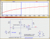
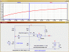
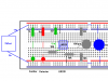
Let me first state that I am a newbie to all this stuff and pulling my hair out over it lol. I am trying to make a Break Beam Sensor to be used in an optical encoder. This is just for fun and to learn and this is how I would like to create the encoder. Anyhow, I have the IR emitter and receiver from Radio Shack, a comparator chip, resistors, capacitors, batteries, wires, etc and a breadboard to put it all together. That last part is where I cannot for the life of me figure it out. I run 5V red wire from battery to a resistor (? not exactly sure why but all the schematics did it with at least a 100 ohm resistor) and from there I run power to the emitter (long side) and the short end of it runs to ground. Just to keep it simple I use another 5V for the receiver and do the same thing, 5V to resistor to long end and short end of receiver to ground.
I still am not sure where the output of the receiver is... assuming the receiver allows voltage to flow when it detects an ir signal and does not when it doesn't, I then try to connect the short end of the receiver to one of the inputs on the comparator chip, which I power 5V and set to ground as well. The comparator chip is even more confusing to me. Some say it outputs digital signal of either 1 or 0 depending on if signal A > signal B. Yet I also read it simply acts as a switch, allowing current to flow from its V+ to GRD. If the latter is true, then why does it have an output? As it stands, I connected the short receiver end to input A, and a source I know to be larger, say a 9V battery to input B (? not sure which end to connect here, I'm assuming the + end and let the - end....dangle?). Now the output for the comparator should then not let any voltage through... but it does not matter how I wire the inputs.... I get the same voltage coming through no matter what. I am testing the voltage using a digital multimeter and testing the output of the comparator with the GRD of the comparator. Please help so I can get some sleep tonight lol
I still am not sure where the output of the receiver is... assuming the receiver allows voltage to flow when it detects an ir signal and does not when it doesn't, I then try to connect the short end of the receiver to one of the inputs on the comparator chip, which I power 5V and set to ground as well. The comparator chip is even more confusing to me. Some say it outputs digital signal of either 1 or 0 depending on if signal A > signal B. Yet I also read it simply acts as a switch, allowing current to flow from its V+ to GRD. If the latter is true, then why does it have an output? As it stands, I connected the short receiver end to input A, and a source I know to be larger, say a 9V battery to input B (? not sure which end to connect here, I'm assuming the + end and let the - end....dangle?). Now the output for the comparator should then not let any voltage through... but it does not matter how I wire the inputs.... I get the same voltage coming through no matter what. I am testing the voltage using a digital multimeter and testing the output of the comparator with the GRD of the comparator. Please help so I can get some sleep tonight lol