Continue to Site

Welcome to our site!

Electro Tech is an online community (with over 170,000 members) who enjoy talking about and building electronic circuits, projects and gadgets. To participate you need to register. Registration is free. Click here to register now.

  • Welcome to our site! Electro Tech is an online community (with over 170,000 members) who enjoy talking about and building electronic circuits, projects and gadgets. To participate you need to register. Registration is free. Click here to register now.

BoostC Charlieplexed PWM 32

Status
Not open for further replies.

Mike - K8LH

Well-Known Member
Would anyone care to study or critique my very first BoostC program?

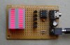
It's a novelty 12F683 program that does 32 PWM brightness levels per LED in a Charlieplexed matrix of 20 LEDs. The refresh rate is 62.5 Hz and each LED duty cycle can be varied from 0% to 20% in thirty two 0.625% (100 usec) steps.

The picture doesn't seem to show the smooth transitions I'm seeing. In fact you can hardly tell those are green LEDs.

Mike

**broken link removed**

**broken link removed**
 

Attachments

  • 12F683_Test_v1.c
    7.3 KB · Views: 761
Last edited:
Very nice indeed. Managing 32 PWM levels on a 4*5 matrix completely in software is impressive. And a good refresh rate as well.

Code wise, I like the way you lay it out, especially the comments. I hate the recent trend of putting comments within a procedure and in the code space ( and on every other line). Your full width comments before and right side comments during a procedure (and initialisation) should be mandatory.

I also like the neatness of the end_of_period and end_of_cycle checks. I'm assuming that you couldn't find a way to avoid the asm - the shift at end_of_period looks like it should be C able.

The only thing I can see that isn't required is the clearing of PIE1.

Overall an excellent example. A++.:D

Mike.
 
WOW!!
Yes, I must agree with Mike(Pommie); this is very well done, and your source is so well commented and very easy to follow.

Mike(Mike, K8LH,) I think you should have an award for getting the most punch out of the least resources!! :D :D :D
 
That's really impressive. I was considering doing something similar with the 8x8 square LED blocks from Futurelec to display patterns, I hadn't considered PWM to dim the lights. I might have to try on a much smaller scale with the Junebug LEDs tonight ;)

What's the board you are using, it looks like a nice size for prototyping or small projects.
 
Gentlemen,

Thank you all for the nice comments.

Pommie,

I'm still trying to come up with optimized C code to replace those remaining few assembler sections. The C code equivalent for those rlf instructions uses two more words and cycles. I guess I'm being a "tightwad" (grin).

edeca,

That's a small Radio Shack proto' board made of phenolic or similar material.

Regards, Mike
 
I use 3.5mm sterio jacks on proto' boards for TTL232 connections.

Sorry about the picture. I tried several different shots, lighting, shutter speeds, etc., trying to show off the smooth fade from about 10% to 100% brightness but never did come up with a good shot. I even tried it with red LEDs (below) but "no joy" as the color is all washed out.

I don't have any video equipment for YouTube. Sorry.

BTW, thanks for turning me onto BoostC. Writing C code for 12F' and 16F' devices for the first time is a blast.

Regards, Mike
 

Attachments

  • PWM-32 Red.jpg
    PWM-32 Red.jpg
    94.5 KB · Views: 625
The green LEDs look good on my monitor. :) The brighter ones are a little washed out but the effect is perfect.

Photography is a lot better than I would normally do. :eek:
 
I don't have any video equipment for YouTube. Sorry.
You have a digital camera!?!? Never seen one yet that won't do video. That's how I do mine.

BTW, thanks for turning me onto BoostC. Writing C code for 12F' and 16F' devices for the first time is a blast.
Kewl, huh? And C code is very very portable from PIC to PIC. I wrote code for 16F88 and with only minor changes ran it on 18F248.
 
Last edited:
Hi Mike, K8LH nice work.

I have a problem.Can you tell me whats the meaning of "Refresh rate is 62.5 Hz"?

I did a small matrix 5X7 recently.I can light up any LED on that.But I don't know what is Refresh rate?
 
I have a problem.Can you tell me whats the meaning of "Refresh rate is 62.5 Hz"?

I did a small matrix 5X7 recently.I can light up any LED on that.But I don't know what is Refresh rate?

The lights are multiplexed (charlieplexed actually) meaning that the code needs to quickly light each segment lots of times per second to give the impression that they are on. In addition the fading means that some need to be on for longer than others, a longer 'duty cycle'.
 
Hi Siraj143,

In multiplexed displays the refresh rate is the number of times per second that an LED is lighted or refreshed. A refresh rate of less than 60 Hz may be perceived as flickering.

Another important factor in multiplexed displays is duty cycle. That's the total amount of time an LED is lighted during a given period expressed as a percentage or a fraction. Duty cycle affects peak and average current requirements to light a display to full brightness. In this case for dimming or fading an LED, we use PWM to change the duty cycle without changing the peak current supplied to the LEDs and this has the effect of changing the "average" LED current and brightness level.

Mike
 
Last edited:
Hi Siraj143,

In multiplexed displays the refresh rate is the number of times per second that an LED is lighted or refreshed. A refresh rate of less than 60 Hz may be perceived as flickering.

Another important factor in multiplexed displays is duty cycle. That's the total amount of time an LED is lighted during a given period expressed as a percentage or a fraction. Duty cycle affects peak and average current requirements to light a display to full brightness. In this case for dimming or fading an LED, we use PWM to change the duty cycle without changing the peak current supplied to the LEDs and this has the effect of changing the "average" LED current and brightness level.

Mike

Hi thanks for the explanation now I understood.If I flash an LED 50 times per second it will show us a flickering.But if I flash it 60 times per second it will stay like a charm without noticing any flicker.

OK for one bulb is ok I understood.

Let say I have multiplexed 5 columns so I have called 5 delays in between them.

In this situation the refresh rate is given to the whole multiplex routine (5 columns) or to a single column?
 
Refresh Rate = 1 / (column1period + column2period + column3period + column4period + column5period)
 
Last edited:
Kewl, huh? And C code is very very portable from PIC to PIC. I wrote code for 16F88 and with only minor changes ran it on 18F248.
Slightly off topic but...

I've been following your progress on the Clock/Calendar/Thermometer project (with Predko 2-pin 74LS174 LCD interface) and I suspected that you didn't have to change much code when porting from the 16F88 to the 18F248. Very nice project and writeup btw (as always)...

Would you consider testing my DayOfWeek routine now that you have calendar capability?

Mike

Code:
unsigned char Month = 6;         // 1..12
unsigned char Day = 18;          // 1..31
unsigned char Year = 08;         // 0..99 (2000-2099)

//  71 instructions on 12F683 (BootsC 16)

unsigned char DayOfWeek()        // Mike McLaren, K8LH, Aug '07
{                                // returns 0..6 (Sun..Sat)
  unsigned char Leap = 0;
  const char Base [] = { 5, 1, 1, 4, 6, 2, 4, 0, 3, 5, 1, 3 };

  Leap = (Year & 3) || (Month > 2);
  return (Base[Month-1] + Day + Leap + Year + Year/4) % 7;
}
 
Last edited:
Mike,

I can confirm your algorithm works correctly until 1st March 2100.

I wrote a little excel sheet to confirm it.:D

Mike.
 
I breadboarded Mike's creation, going by the schematic he provided. Holy hell!!! That's a lot of wires to squeeze onto a little breadboard! As you can see, I gave up keeping it neat after a while. Just too many...
mike_led002_800x600.jpg
The switches switch GP0 and GP1 between programming mode and run mode.

But it doesn't work!! :confused: Some LEDs light, but no action.

Mike! How accurate is that schematic? It doesn't say the resistor values, so I did some educated guessing.
 
Sorry you're having problems.

Transistors are 2N3904 NPN. Most people see that they're sourcing drivers and assume they're PNP (because the drawing is so fuzzy).

I originally used 510 ohm base resistors and 20 ohm current limiting resistors on the rows but the board in the picture has been taken apart so many times that there are NO resistors at all at the moment. Bad practice I know. It just shows how forgiving this stuff is...

Let me know how it goes?

Mike
 
Last edited:
Status
Not open for further replies.

Latest threads

Back
Top