Califauna
Member
Hi,
I have a W-King D8 Bluetooth boom box which I'd like to modify with some external speaker output jacks and some buttons to switch the internal speakers on and off.
From factory the specs of the boom box are:
-Power Input: DC 5V
-Speaker Output Power: 2 x 25W ( confirmed by Youtube channel Hartdegen review as 12.5W RMS per channel)
-Drivers:
-2 x Woofer, 70mm, 10Ω, 70mm,15W
-2 X Tweeter, 8Ω, 30mm,10W x 2
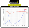
-Frequency Response: 60Hz - 20kHz
-Battery Type: Li-ion ( 2 x 4000mAh)
-Battery Voltage: 7.4V ( I measured 8v)
-True Wireless Stereo (TWS): Support
-Technology: BT4.2, A2DP, AVRCP, HSP, HFP.
-The measured resistance at each amplifier output (amp side, speakers disconnected) is 1.2 million ohms.
The tweeters have a resistor in parallel creating a passive high-pass filter.
Here are the circuit diagrams from factory and for the modification I'd like to make.
Factory:
Diagram 1.

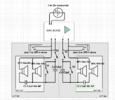
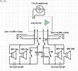
And here with my modification:
Diagram 2.

As you can see, I have added:
1. Jacks to connect to external speakers.
2. A higher level high pass filter function on each side (HPF #3 and #4), within which you can see that the factory high-pass HPF #1 and #2 are also nested.
3. Switches 1 and 4, which (I hope) allow the built in speakers to be switched into the passive high pass filter configuration which I have added , using capacitors 2 and 3. This could be handy when connecting to external speakers which can better handle the bass part of the audio. For calculating the value of capacitors 2 and 3 in these added HPFs, I have considered the added external speakers (connected through the jacks) to be the 'resistor', and that this external speaker nominally has an impedance of 4 ohms. Regarding this I have some questions below.
4. Switches 3 and 4, which allow the built-in speakers to be turned off entirely (eg. when I want only external speakers to be used).
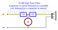
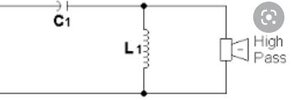
Regarding the HP filter, typical diagrams and explanations are that a resistor is ALWAYS necessary in parallel with the load (in this case a speaker through which passes filter audio), sometimes with a connection to ground. Eg:
Diagram 3.

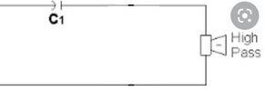
Firstly, I do not understand why a resistor (external speakers) is always necessary for a filter like this to work and wonder whether it could work without them. Indeed, according to this book, the simplest form of a high pass filter has no resistor:
Diagram 4.

Among the explanations of why a resistor is included in such filter circuits, I have read that 'it is to avoid 'thump' when connecting a load, and to allow a steady state at all times' (+ capacitor capacitor always able to discharge) . However, I am not concerned about an initial 'thump' when connecting a speaker. Also I don't see why this 'steady state', or continually being able to discharge/charge is necessary or advantageous. Actually I see that as a disadvantage potentially, as the amplifier/battery power is being left to drain away through such a resistor completing the circuit (?), even when the external speaker is not connected.
FFI also see explanations indicating that a resistor helps prevent current leaks to ground, as in the picture above with ground connection. However, as it is a portable speaker in this case, there is no ground connection, so why would a resistor be necessary there?
Another explanation I've read is that "if you want to predict the filter's performance you need to know how much resistance is in series with the signal. A theoretical source with zero impedance will not be affected by the capacitor. If the signal is coming from something which has significant output impedance, then an additional resistor may not be needed."
Regarding that explanation, I DO know the resistance which is in series with the signal, (4ohms - not a theoretical 0 ohms), so why the need for an additional resistor in parallel with it?
I also have the following questions:
I figure that the addition of capacitors C3 and C4 will continuously affect the cutoff frequency of HPF#1 and #2 (factory installed HPFs), which filter the signal to speakers 1 and 4, because the resistance of the parallel 'resistor' each sees will vary. I figure this because, taking HPF#3 for example, the 'resistor' it sees when speaker 5 is connected and switch 1 is open will no longer be just speaker 2, but the combined resistance of speaker 2, capacitor 3, and speaker 5 all in parallel. Thus the 'resistor' of HPF#1 will vary continuously as the frequency of the signal into capacitor 3 changes (the changing audio signal). Perhaps it will also be affected slightly by varying amounts of back EMF produced by speakers 2 and 5? How much is all this likely to affect the filtered output of speaker 1 in this scenario?
Will typical 3.5 mm audio jacks be able to handle the current flowing through speakers 5 and 6? I also have phono plugs, but there isn't much space to work with inside the enclosure part where the electronics are, so I'd like to go with smallest components if possible. I'm also not sure what rating the switches would have to meet. When S1 and S2 are closed and SP5 is connected, I have calculated that theoretically the peak current through switch 1, switch 2, and jack 1 (when all the signal is above the cut-off frequencies), would be I=V/R = 7.4v / (1/((1/8Ω)+(1/10Ω)+(1/4Ω)) = 3.515a. This is ignoring any back EMF induced in the speakers (if indeed this is a real issue).
I notice the rating for switches is often higher when used in 110 Volts circuits than when the same switch is used in a 240v circuit. Is this something to do with the rating being partly determined by the power (P=IV), not just the current flow through the component?
Am I right in thinking capacitor 3 will do nothing (remain infinite resistance) when switch 1 is closed?


Thanks for your explanations, corrections, suggestions, and possible additional ideas/functionalities that might be useful and could be added while the box is open.
I have a W-King D8 Bluetooth boom box which I'd like to modify with some external speaker output jacks and some buttons to switch the internal speakers on and off.
From factory the specs of the boom box are:
-Power Input: DC 5V
-Speaker Output Power: 2 x 25W ( confirmed by Youtube channel Hartdegen review as 12.5W RMS per channel)
-Drivers:
-2 x Woofer, 70mm, 10Ω, 70mm,15W
-2 X Tweeter, 8Ω, 30mm,10W x 2
-Frequency Response: 60Hz - 20kHz
-Battery Type: Li-ion ( 2 x 4000mAh)
-Battery Voltage: 7.4V ( I measured 8v)
-True Wireless Stereo (TWS): Support
-Technology: BT4.2, A2DP, AVRCP, HSP, HFP.
-The measured resistance at each amplifier output (amp side, speakers disconnected) is 1.2 million ohms.
The tweeters have a resistor in parallel creating a passive high-pass filter.
Here are the circuit diagrams from factory and for the modification I'd like to make.
Factory:
Diagram 1.
And here with my modification:
Diagram 2.
As you can see, I have added:
1. Jacks to connect to external speakers.
2. A higher level high pass filter function on each side (HPF #3 and #4), within which you can see that the factory high-pass HPF #1 and #2 are also nested.
3. Switches 1 and 4, which (I hope) allow the built in speakers to be switched into the passive high pass filter configuration which I have added , using capacitors 2 and 3. This could be handy when connecting to external speakers which can better handle the bass part of the audio. For calculating the value of capacitors 2 and 3 in these added HPFs, I have considered the added external speakers (connected through the jacks) to be the 'resistor', and that this external speaker nominally has an impedance of 4 ohms. Regarding this I have some questions below.
4. Switches 3 and 4, which allow the built-in speakers to be turned off entirely (eg. when I want only external speakers to be used).
Regarding the HP filter, typical diagrams and explanations are that a resistor is ALWAYS necessary in parallel with the load (in this case a speaker through which passes filter audio), sometimes with a connection to ground. Eg:
Diagram 3.
Firstly, I do not understand why a resistor (external speakers) is always necessary for a filter like this to work and wonder whether it could work without them. Indeed, according to this book, the simplest form of a high pass filter has no resistor:
Diagram 4.
Among the explanations of why a resistor is included in such filter circuits, I have read that 'it is to avoid 'thump' when connecting a load, and to allow a steady state at all times' (+ capacitor capacitor always able to discharge) . However, I am not concerned about an initial 'thump' when connecting a speaker. Also I don't see why this 'steady state', or continually being able to discharge/charge is necessary or advantageous. Actually I see that as a disadvantage potentially, as the amplifier/battery power is being left to drain away through such a resistor completing the circuit (?), even when the external speaker is not connected.
FFI also see explanations indicating that a resistor helps prevent current leaks to ground, as in the picture above with ground connection. However, as it is a portable speaker in this case, there is no ground connection, so why would a resistor be necessary there?
Another explanation I've read is that "if you want to predict the filter's performance you need to know how much resistance is in series with the signal. A theoretical source with zero impedance will not be affected by the capacitor. If the signal is coming from something which has significant output impedance, then an additional resistor may not be needed."
Regarding that explanation, I DO know the resistance which is in series with the signal, (4ohms - not a theoretical 0 ohms), so why the need for an additional resistor in parallel with it?
I also have the following questions:
I figure that the addition of capacitors C3 and C4 will continuously affect the cutoff frequency of HPF#1 and #2 (factory installed HPFs), which filter the signal to speakers 1 and 4, because the resistance of the parallel 'resistor' each sees will vary. I figure this because, taking HPF#3 for example, the 'resistor' it sees when speaker 5 is connected and switch 1 is open will no longer be just speaker 2, but the combined resistance of speaker 2, capacitor 3, and speaker 5 all in parallel. Thus the 'resistor' of HPF#1 will vary continuously as the frequency of the signal into capacitor 3 changes (the changing audio signal). Perhaps it will also be affected slightly by varying amounts of back EMF produced by speakers 2 and 5? How much is all this likely to affect the filtered output of speaker 1 in this scenario?
Will typical 3.5 mm audio jacks be able to handle the current flowing through speakers 5 and 6? I also have phono plugs, but there isn't much space to work with inside the enclosure part where the electronics are, so I'd like to go with smallest components if possible. I'm also not sure what rating the switches would have to meet. When S1 and S2 are closed and SP5 is connected, I have calculated that theoretically the peak current through switch 1, switch 2, and jack 1 (when all the signal is above the cut-off frequencies), would be I=V/R = 7.4v / (1/((1/8Ω)+(1/10Ω)+(1/4Ω)) = 3.515a. This is ignoring any back EMF induced in the speakers (if indeed this is a real issue).
I notice the rating for switches is often higher when used in 110 Volts circuits than when the same switch is used in a 240v circuit. Is this something to do with the rating being partly determined by the power (P=IV), not just the current flow through the component?
Am I right in thinking capacitor 3 will do nothing (remain infinite resistance) when switch 1 is closed?
Thanks for your explanations, corrections, suggestions, and possible additional ideas/functionalities that might be useful and could be added while the box is open.
Attachments

Last edited: