Continue to Site

Welcome to our site!

Electro Tech is an online community (with over 170,000 members) who enjoy talking about and building electronic circuits, projects and gadgets. To participate you need to register. Registration is free. Click here to register now.

  • Welcome to our site! Electro Tech is an online community (with over 170,000 members) who enjoy talking about and building electronic circuits, projects and gadgets. To participate you need to register. Registration is free. Click here to register now.

BJT question

Status
Not open for further replies.

jack23

New Member
Hello all,

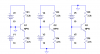
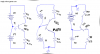
I have a question regarding the BJT configuration that I have posted. The values I had to find were the current Ie and the voltage V3, which is the same as Vc.

The answers are: Ie = Ve - (-10v) / 4.7K = 2mA

Vc = 10V - IcRc = 10V - 2MA*(3.3K) = 3.4V


these answers are correct. But what I am confused about is the following:

When I first look at this simple circuit, I see that the base is tied to ground. So to me, that mean that there is no current going into the base, therefore the transistor is in cut-off. If it is in cut-off, then the transistor behaves as an open switch and there-for no current through the collector or emitter.

i know I am wrong here, but this is my first assumption when I first look at it. Can someone shine some light for me here. Thanks
 

Attachments

  • scan0002.pdf
    86 KB · Views: 142
If the emitter was connected to 0V then what you are saying would be true as it isn't at 0V but -10V. The base is at 0V and the emitter is connected to -10V via a resistor meaning current is flowing from 0V to -10V.
 
Hero999 said:
If the emitter was connected to 0V then what you are saying would be true as it isn't at 0V but -10V. The base is at 0V and the emitter is connected to -10V via a resistor meaning current is flowing from 0V to -10V.

So, it does not matter if the base is connected to 0V, as long as the Base-Emitter junction is forward biased. Which in this case it is because the N-type emitter is at a lower voltage potential than the P-type Base. Correct?

Of course, the above statement is assuming the Collector-Base junction is reverse biased.
 
jack23 said:
So, it does not matter if the base is connected to 0V, as long as the Base-Emitter junction is forward biased. Which in this case it is because the N-type emitter is at a lower voltage potential than the P-type Base. Correct?

Of course, the above statement is assuming the Collector-Base junction is reverse biased.
Ground is just an arbitrary reference point. Look at the 3 circuits below. The transistor quiescent point is exactly the same in all three.
 

Attachments

  • BJT biasing.PNG
    BJT biasing.PNG
    12.6 KB · Views: 149
It makes me dizzy to see the ground bouncing around like that. Earthquake?
 
audioguru said:
It makes me dizzy to see the ground bouncing around like that. Earthquake?
Yep. It all started like this...
 

Attachments

  • bjt earthquake.png
    bjt earthquake.png
    55.8 KB · Views: 119
Status
Not open for further replies.

Latest threads

New Articles From Microcontroller Tips

Back
Top