Continue to Site

Welcome to our site!

Electro Tech is an online community (with over 170,000 members) who enjoy talking about and building electronic circuits, projects and gadgets. To participate you need to register. Registration is free. Click here to register now.

  • Welcome to our site! Electro Tech is an online community (with over 170,000 members) who enjoy talking about and building electronic circuits, projects and gadgets. To participate you need to register. Registration is free. Click here to register now.

BJT linear region calculations

Status
Not open for further replies.
HolyMustard said:
i'm just wondering how it's working without generating mass heat or even blowing up? cuz by what you guys are saying is the transistors are being worked hard or that it shouldn't even work? (could it be that i'm not actually running it continuously for more than 2secs?)
You said the supply is 14V to 24V but you also say it is a motor from a toy car. I've never seen a toy operate on 24V!

The motor has spec's for how much heat it can dissipate, transistors also have heat spec's. The amount of heat is calculated from the voltage across it times the current through it.

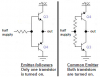
The base resistors were a high value so the transistors didn't turn on very well. Therefore the motor didn't get anywhere near the full supply voltage and was saved from burning up.
 
Hi,
I don't know I'm right or not, but there is difference with what I've learned. The load should be connected to the collector right? So the position of NPN and PNP should be changed?
 
bananasiong said:
Hi,
I don't know I'm right or not, but there is difference with what I've learned. The load should be connected to the collector right? So the position of NPN and PNP should be changed?
You had the transistors used as emitter-followers that each has a loss of about 0.7V. If they are reversed so the load is at the collectors then the loss is much less, but when switching motor directon both sets of transistors are turned on at the same time which shorts the supply and might blow up the transistors.

Motor driver ICs have "dead time" so that one transistor is turned off before the other transistor is turned on.
 
yea it would have been better to connect the load on the collector side but then the drive circuit is a little more complicated as you have to make sure the transistors don't turn on at the same time. yea i was kinda of confused as to implementing dead time or whether that was implied.

well the motor i was given might not be a toy motor exactly but it's the same size as one. and the specifications i have given you are the ones that were given to me. but the thing is, i'm pretty sure the loss in the transistors with the 270ohm aren't greater than 1.4V (because i have 2 transistors in the path) as when i connect the motor directly to a 24V supply the speed dicrepancy is not noticable.
 
I was talking about the motor accellerating or working hard, maybe stalled, then its current is 600mA. You tested it without a load when its current is very low, then the 270 ohm resistors give the transistors enough base current for them to conduct enough.
 
o ok. so is there any way i can actually use this circuit effectively? in otherwords calculate the resistor values so that it will function properly? or is the set up so ineffective that i shouldn't even pursue this meathod?
 
HolyMustard said:
o ok. so is there any way i can actually use this circuit effectively? in otherwords calculate the resistor values so that it will function properly? or is the set up so ineffective that i shouldn't even pursue this meathod?
Use NPN darlington power transistors for Q3 and Q5 in your original circuit. Then their current gain will be high enough for them to saturate. Their saturation voltage will be about 1.5V in your circuit.
 
but even still the trasistor won't be able to run in the saturation region because there is no collector resistor? and i thought how you bias a transistor into the saturation region is via the size of your collector resistor? or are you meaning providing enough base current to drive the transistor to max Ic in the linear region? and also when you say 1.5V is that the low power transistors (drive transistors) or the high power transistors? cheers.
 
HolyMustard said:
but even still the trasistor won't be able to run in the saturation region because there is no collector resistor? and i thought how you bias a transistor into the saturation region is via the size of your collector resistor? or are you meaning providing enough base current to drive the transistor to max Ic in the linear region? and also when you say 1.5V is that the low power transistors (drive transistors) or the high power transistors?
Your power transistors are used as emitter-followers. They don't use a collector resistor because the load is at their emitters and is about 0.8V less than the base voltage. The transistors need a base current of 1/10th the max current of the motor to turn on fully but the current is severely limited by the base resistors so the upper power transistors don't turn on hard enough.

If power darlington transistors are used instead of ordinary power transistors for the two at the top (Q3 and Q5) then they have much more current gain so the base resistors supply plenty of base current for them to saturate for a loss of about only 1.5V.
 
yep that makes sense.

another question: if i were to run collector followers and had enough base resistance to drive the transister, that would mean i would be operating the transistor in the saturation region right? which would mean i only have approx. 0.1V loss across each transistor? as opposed to my current configuration of emitter followers which run in the linear region which cause it to have a 0.7V loss across each transistor, right?
 
HolyMustard said:
another question: if i were to run collector followers and had enough base resistance to drive the transister, that would mean i would be operating the transistor in the saturation region right? which would mean i only have approx. 0.1V loss across each transistor? as opposed to my current configuration of emitter followers which run in the linear region which cause it to have a 0.7V loss across each transistor, right?
There is no such thing as "a collector follower", it is called a common emitter stage. The loss is only 0.1V or less at low collector current. At the 600mA max current of your motor, your BD139 transistor has a typical saturation voltage of 0.4V or 0.6V max when its base current is 60mA.
As an emitter-follower with a 600mA load its loss is typically 0.8V or 1V max, plus the loss in the base resistor.

You can't operate the transistors in your circuit as common emitter stages because both top and bottom transistors will be turned on at the same time when they switch.
 
yeah the 1st paragraph makes sense.

but the 2nd paragraph kinda confused me a little. when you say i can't use the common emitter stages are you implying i'm using all NPN transistors? because i'm using NPN at the top and PNP for the bottom so when the drive transistors are pushing current only the top NPN transistor will turn on will the bottom PNP transistor remains off. When drive transistors pull current top transistors turn off while bottom turns on.

or are you referring to dead time?
 
Your circuit uses complimentary emitter-follower transistors with their bases connected together. Since their bases are connected together then the top NPN and the bottom PNP cannot both be turned on at the same time which would happen if they are complementary common emitter transistors. If they turn on at the same time then they are a short circuit across the supply with very high current. Dead time would prevent both from turning on at the same time during switching.
 
You can't operate the transistors in your circuit as common emitter stages because both top and bottom transistors will be turned on at the same time when they switch.

whats the difference between my circuit (emitter-follower) and that stated above (common-emitter)?
 
HolyMustard said:
whats the difference between my circuit (emitter-follower) and that stated above (common-emitter)?
Maybe you will see the problem in a schematic:
 

Attachments

  • h-bridge.PNG
    h-bridge.PNG
    17.3 KB · Views: 133
o ok cheers. how come for the common-emitter both transistors turn on? doesn't a PNP transister require current drawen from the base and a NPN requires current pushed into the base? therefore only one transistor should turn on at a time like the emitter-follower.
 
Both common-emitter transistors have base current and therefore are both turned on, shorting the supply.
For the emitter-followers, if one transistor has base current and is turned on, then the other transistor has its base-emitter reverse-biased and therefore doesn't have any base current.
 
o ok. that clarifies everything.

Hey thanks for all your help and being so patient Audioguru. You really helped me understand the situation alot better. cheers your a legend.

And thanks to everyone else's help aswell.
 
Status
Not open for further replies.

Latest threads

New Articles From Microcontroller Tips

Back
Top