Electro Tech is an online community (with over 170,000 members) who enjoy talking about and building electronic circuits, projects and gadgets. To participate you need to register. Registration is free. Click here to register now.
Welcome to our site! Electro Tech is an online community (with over 170,000 members) who enjoy talking about and building electronic circuits, projects and gadgets. To participate you need to register. Registration is free. Click here to register now.
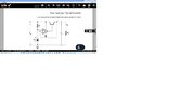
The opamp compares the output voltage to the zener reference voltage and the opamp output will go high or low if the voltage is low or high (as the voltage sensing is on the inverting input).
That acts to adjust the transistor base drive and hold the regulator output at a constant voltage, within a fairly limited range of current.
eg. It may be OK for a few hundred mA with an appropriate transistor, but not high currents as most opamps can only give fairly small output currents, something probably in the 10mA to 50mA range depending on the type.
The opamp would also have to be suitable for the voltage range involved; some can't take above 3 - 5V, other can operate on 40V or more.
Thanks a lot!
What is the output of the op-amp?
Is there any effect on the output of the op-amp; from the non-inverting side?
and why the voltage to the Base of the transistor decreases when VL increase?
So actually you say that when the voltage in the inverting side increases;
the output voltage of the op-amp will decrease in order to make equal V(+) and V(-)?
thanks a lot
So actually you say that when the voltage in the inverting side increases;
the output voltage of the op-amp will decrease in order to make equal V(+) and V(-)?
Thanks a lot!
What is Vi; in my circuit?
So why: VL=Vz-Vi in my circuit?
Why, in a op-amp, whose voltage gain is infinite, the voltage Vi tends to zero?
Thanks
let A= 10^5 (typ BJT Op Amp) and VL=Vz since closed loop gain = 1 as there is no attenuation to Vi- negative feedback. . Non-inverting gain = 1+ |inverting gain=0|=1. But we hope Vz is constant, but italso has some series resistance so it varies much less than Vin.
If VL-Vz= small error,E then Vi= E/10^5 thus Vi~0 however if OpAmp has input offset, in uV or mV that too will be added to output error, E. In datasheets input offset error= Vio
And of course there is error due to PSRR and Vbe and OpAmp Rout but for the
simple circuit and crappy tolerances of Vz most designs, I would posit, would not
care given the approach used. Not counting AC effects and noise as well.
Thanks a lot!
VL=A(Vz-Vi)
VL-is the output of the circuit
Whereas Vi is the input of the negative side of the op-amp.
But you assumed that VL and Vi is the same thing
and it is not correct.
IL*RL=VL is the output of the circuit
Thanks
This site uses cookies to help personalise content, tailor your experience and to keep you logged in if you register.
By continuing to use this site, you are consenting to our use of cookies.