Continue to Site

Welcome to our site!

Electro Tech is an online community (with over 170,000 members) who enjoy talking about and building electronic circuits, projects and gadgets. To participate you need to register. Registration is free. Click here to register now.

  • Welcome to our site! Electro Tech is an online community (with over 170,000 members) who enjoy talking about and building electronic circuits, projects and gadgets. To participate you need to register. Registration is free. Click here to register now.

How to use linear optocoupler

Status
Not open for further replies.

Fluffyboii

Active Member
1668794993413.png
IMG_20221118_210219.jpg

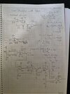
Circuit requires some DC offset so I implemented a summing amplifier. The thing I am not understanding is to how to choose resistor values.
Looking at the graph for 6V I need 460 ohm led resistor. Can I impose my input signal over 5.5V DC like this and calculate for 5.5V + 0.5V signal. The servo photo diodes are even more confusing since its gain is very low acording to datasheet. Shouldn't currents passing through both of them be the same. At 10mA "If" current 100uF is passing through photo diode so how can I pick the R1 and R2 values according to this information. Should I just use 60K so that 100uA is passing through the resistor or is there a other way of calculating this. The op amp setup with no feedback is confusing too.
1668795394965.png
 
The summing amp can be a single stage with 50K feedback to give unity gain.

The photodiode cathodes go to a positive supply! They work in reverse bias (photoconduction) mode.

The current through the two photodiodes should be identical, or very close, for any reasonable level of LED current.
That's how the coupler works; the driver opamp sets whatever LED current is needed for the voltage across the load resistor to equal the signal input voltage.

With matched photodiodes in the device and equal load resistors, that same voltage will appear across the load resistor on the output side, so duplicating the input signal.

You could add an inverting differential amp after the original circuit output, to remove the added offset. The offset only needs to be eg. 1V to keep the signal fully in the working range of the circuit.

And be sure to use opamps with very low input currents!
Our lab only has lm741 and TL081 and half of them are blown up, combined with worn out breadboards noting works. I will bring my own TL074 and breadboard and make it bit easier. That is why I used two inverting op amps for adding bias instead of one since I have 4 at my disposal. So should I use a single non inverting summing op amp at the input? Since Optocoupler opens after 1.1V I would need around 1.25V bias but when 0.5V input signal is at its peak it will go up to much or go too low when it is reversed, which would pass its maximum 1.5V rating. For that reason I picked dc bias 5.5V and used a resistor in series with the LED to limit current to 10mA or I will just use a op amp with lower than unity gain. There must be some kind of attenuation at input since 500mV is too much on its own if I will bias it around 1V. Also I never seen VCC mean VDD before :/ What about R1 and R2. They will be same but what I need to consider while picking them. I can also use one op amp for adding bias and another at the output to subtract as you said.
 
Would this work? First inverting summing amplifier adds -1V to signal so that at the output it is something around 1V. Then reverse is applied at the output.
 

Attachments

  • IMG_20221119_140310.jpg
    IMG_20221119_140310.jpg
    782.8 KB · Views: 189
That looks OK in principle, though you must have higher value load resistors on the photodiodes.

With a 1K feeding the LED, it's limited to around 10mA max, and at that only about 100uA output, so around 500 - 600mV absolute maximum signal handling with 5.6K loads.

I'd say a minimum of 22K with that drive circuit, to get at least a couple of volts signal range.

If the opamp output can provide more than 10mA you could also reduce the LED resistor a bit to give more signal headroom.
 
1668872201536.png
1668872214534.png

Looking at these two graphs of TL074 it looks like maximum I can get is about 10mA maybe 13 if I am lucky if I am not wrong. I will try changing those 5.6K resistors with something higher as you said.

Edit: Thinking about it, how can be the LED current be 15mA with +-15V op amp supply anyway. Assuming it will be 10mA R1 and R2 should be 10K. Since LED will add some additional resistance I think 22K is more appropriate as you said. There is only one thing I don't understand though which is how the LED current is related with the input voltage. Since there is no feedback for the first amplifier, output voltage would be multiplied by its own gain which is more than 1000 so it would always max out at output from my understanding and wouldn't change with input voltage. Input is mirrored to its other input and there is the photodiode curent added there, it is just confusing.
 
Last edited:
But there is from the second sensor diode.
Makes sense. Servo diode has current gain of 0.012. Can I calculate the gain of the first stage with this information. I need to check Op Amp section of my books, I never understand exactly how it works at the end.

Ok if I use the knowledge of that inverting input will have same voltage with input which is 1V in this example and just use the current ratio I can indeed understand with 10K R1 it will have 8.3mA LED current and 100uA servo current. which will be mirrored to other servo if R2 is 10K and it will have same output voltage. Which makes sense. When my input signal which is 0.5V peak to peak maximum voltage will be 1.5V. It will have 12.5mA passing through LED and 150uA servo current. Which is fine. At the lower end it will be 0.5V and 4.1mA Led current and 50uA servo current. It should work according to datasheet.
 
Last edited:
There is only one thing I don't understand though which is how the LED current is related with the input voltage. Since there is no feedback for the first amplifier, output voltage would be multiplied by its own gain which is more than 1000 so it would always max out at output from my understanding and wouldn't change with input voltage. Input is mirrored to its other input and there is the photodiode curent added there, it is just confusing.

The maximum LED current defines the photodiode current.

With 10mA max at the LED, the photodiode current could be as low as 75uA. That MUST create enough voltage across the photodiode load resistors to keep the signal in range.

The maximum signal voltage is 1.5V so the load resistors must drop somewhat more than 1.5V at 75uA, to be safe and keep everything within working range.

That's 20K minimum!

22K is only allowing a small amount of headroom & the absolute minimum, 27K or 33K would not hurt it.


I don't follow what you mean by "there is no feedback for the first amplifier"? Every stage has feedback?
 
I don't follow what you mean by "there is no feedback for the first amplifier"? Every stage has feedback?
The fact that it is not like the textbook examples and there is technically no connection between LED and photodiode is confusing for someone that usually doesn't fully understand electrical concepts but memorise to survive in college like me. I now get that there is feedback after all and it can probably be replaced with an equivalent resistor network. Are my latest calculations incorrect?
The maximum signal voltage is 1.5V so the load resistors must drop somewhat more than 1.5V at 75uA, to be safe and keep everything within working range.

That's 20K minimum!

22K is only allowing a small amount of headroom & the absolute minimum, 27K or 33K would not hurt it.
Wouldn't a larger resistor decrease LED current since it needs to be equal with input voltage at the inverting input. Being safe and keeping in working range means not passing max LED current, right?
1668980162778.png

Isn't the only limiting factor here is the maximum current capability of the TL074.
 
Last edited:
Isn't the only limiting factor here is the maximum current capability of the TL074.
Not quite; with the 1K resistor you use for the LED and the maximum loaded output of the TL074, less the LED voltage drop, there is not much more than 10V guaranteed across that 1K, so a hard limit of about 10mA through it. That's why I suggested a lower resistor, if the opamp could guarantee a higher output current.

And yes, a higher photodiode load resistor will mean it requires less LED current for a given signal level.
Ah yes at 1.5V max input voltage it may be problem with that current limit. TL074 can probably push bit more than 10mA even though datasheet says otherwise since I saw it fully light up one LED before with 1K series resistor. Maybe I can push my luck and change the 1K resistor with something like 820. Changing R1 and R2 with something more probably makes more sense. Need to test in real life, will report after lab session.
 
Not quite; with the 1K resistor you use for the LED and the maximum loaded output of the TL074, less the LED voltage drop, there is not much more than 10V guaranteed across that 1K, so a hard limit of about 10mA through it. That's why I suggested a lower resistor, if the opamp could guarantee a higher output current.

And yes, a higher photodiode load resistor will mean it requires less LED current for a given signal level.
1668981611679.png

Looks like it is even worse. 10V swing with 2K and more.
 
Below is the LTspice simulation of the basic circuit shown in the app note:
The sim uses an ideal op amp, and the opto model (from Vishay) has a K1 and K2 current transfer ratio of 0.012 to both detectors (K3=1).

Edit: Model changed for the simulation below to use the typical value of 0.009 for K1 and K2.
And an observation: The R1 resistor at the output of the op amp is not needed unless the op amp can output more than the 60mA maximum of the IL300 input, since the feedback, not R1, determines the current into its input (in this case, 1 / .009 = 111 times the current through R2).


1669058445877.png
 
Last edited:
For anyone interested, below are the IL300 LTspice files I used for the symbol and model:
The model was slight modified to correct some errors and get it to work properly in LTspice.
 

Attachments

  • IL300.sub
    4 KB · Views: 199
  • IL300.asy
    1.4 KB · Views: 193
Last edited:
Fluffyboii, if you haven't used a simulator, I suggest you download the free LTspice program from Analog Devices.
I think it will help you design and understand a circuit before you build it.
LTspice has a somewhat steep learning curve, but there are good tutorials and example circuits to help with that, and we are always here to answer questions.
 
Last edited:
Status
Not open for further replies.

Latest threads

Back
Top