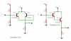
can some one help me understand the calculation made on link
BJT Amplifier | Scienceray
because i want to understand common collector so that i can use it in my circuit. where i am getting 8v(RMS) and 4mA at the output of my circuit. i want to amplify it to atleast 100mA with same voltage.
BJT Amplifier | Scienceray
because i want to understand common collector so that i can use it in my circuit. where i am getting 8v(RMS) and 4mA at the output of my circuit. i want to amplify it to atleast 100mA with same voltage.
Attachments

Last edited: