Continue to Site

Welcome to our site!

Electro Tech is an online community (with over 170,000 members) who enjoy talking about and building electronic circuits, projects and gadgets. To participate you need to register. Registration is free. Click here to register now.

  • Welcome to our site! Electro Tech is an online community (with over 170,000 members) who enjoy talking about and building electronic circuits, projects and gadgets. To participate you need to register. Registration is free. Click here to register now.

Bistable Flip Flop (Change Over Cct)

Status
Not open for further replies.

Gayan Soyza

Active Member
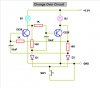
Here is a Bistable flip flop circuit in another way.It can call as a Change Over Circuit.So many circuits I tried to get nice latch functions.Here is my final Solution.It has done by thinking deeper in the normal Bistable Latch.

Every time the button pressed the bulbs change its state.Same like normal
Bistable Latch.Replacing one bulb can Act as a latch cct.

May be you guys have experienced same like this.
 

Attachments

  • Change Over Circuit.JPG
    Change Over Circuit.JPG
    41.2 KB · Views: 1,650
This circuit is 35 years old instead of 45 years old. It is simpler but does about the same. The inexpensive IC can make 4 of them.
 

Attachments

  • Alternate-action.gif
    Alternate-action.gif
    3.6 KB · Views: 783
And I can get what? Six RS flip-flops on a TTL chip? Why all the discretes?

Dean
 
I have tried these IC's cd 4027,cd 4013, sn 7474, sn 7473 its working but it has switching delays.thats why I used transistors.but I have not tried that cd 4069 one.I must try that cct.anyway thankx for the diagram.
 
audioguru said:
This circuit is 35 years old instead of 45 years old...

Don't shoot me !
I'll show you a circuit more than... 55 years old. I have tried this many years ago, and I used it in many applications, also, I found it in many old industrial equipments.
This circuit does not have switching delays, and its work is based on a feature of the traditional relays.

See ChangeOverCircuit.png
See also https://emil.matei.ro/onof2.php
 

Attachments

  • ChangeOverCircuit.png
    ChangeOverCircuit.png
    5.4 KB · Views: 664
Interesting relay circuit.
An electronic flip-flop circuit more than 55 years old that doesn't use any electronic parts.
 
This circuit is different to the one I recall being posted some weeks ago. If I remember correctly, R1 and R2 where not inserted, ie. there were wires in lieu of them.

Obviously they have been added in order to limit the voltage across the relay coil to 6V rather than thump them with 12V.

But as far as I can see, it will not work with the resistors.

When d1 operates, d1.1 connects the coil of d2 in parallel with R2 so d2 will operate whereas it should only operate when the button is released.
 
Both schematics are OK. Choosing one or another shematic depends on used relays type.
If current limiting resistors are not used, the selected relays must safely work in a larger voltage range. For example, relays having V=(0.55...1.1)*Vnominal.

When the pushbutton PB1 is first pressed, only d1 is actuated. Even if d1.1 closes, d2 cannot actuate because coil of d2 is shorted by d2.2+PB1+d2.1.
When the pushbutton PB1 is released, because d1 is energized and d1.1 is closed, the opening of the switch diverts current through the coil d2. Current flows through the coil of relay d1, contact d1.1 and coil d2.

My previous post contains a link to more details.
 
audioguru said:
Interesting relay circuit.
An electronic flip-flop circuit more than 55 years old that doesn't use any electronic parts.

There's been some incredible things built with relays over the years - even full computers are possible.

For that matter, how about 'fluidics', a completely non-electrical logic system. There used to be an old guy in Matlock who ran his own small engineering company, and he used fluidic systems to run his production lines. I presume he's died now?, he was old when we talked about it - and that was the early microprocessor days - he was considering looking into microprocessor control instead. He was a VERY clued up guy, particularly as he must have been in his seventies back then? - no disrespect AG! :p
 
Status
Not open for further replies.

New Articles From Microcontroller Tips

Back
Top