Continue to Site

Welcome to our site!

Electro Tech is an online community (with over 170,000 members) who enjoy talking about and building electronic circuits, projects and gadgets. To participate you need to register. Registration is free. Click here to register now.

  • Welcome to our site! Electro Tech is an online community (with over 170,000 members) who enjoy talking about and building electronic circuits, projects and gadgets. To participate you need to register. Registration is free. Click here to register now.

Bird scarer

Status
Not open for further replies.

Matlix

New Member
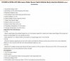
So I'm trying to get a bird scarer done with the use of a 555 and RCWL-0516(microwave sensor) and a 9V solar panel , but I can't figure out how to properly implement the RCWL into the circuit.
I was thinking about doing it with an Arduino, but from what I've read it should be able to work with a 555 IC + I'm not sure if the 9V will be enough

I know that the diode will take +- 0.7V (I put it there to stop reverse voltage, yet I dunno if it's ok)
I'm also not sure about the resistors and capacitators, cuz I tried to re-do a timer circuit.
And also I dunno if the RCWL should be connected as it is.

Thanks for the answers
BS.JPG
 
Note that the RCWL-0516 "Vin" must be 5V within a few percent; you cannot run it directly from a 9V solar panel.
If it has been connected to 9V it may have been damaged.

Add a decent size electrolytic capacitor between Vin and GND; GND should be connected to the overall ground and 555 VCC should also go to the 5V supply.

The OUT terminal should feed the resistors linked to the 555 to enable/disable oscillation.

For the 555, the "discharge" pin should be linked to the junction between the two resistors, or it will not oscillate.
See some of the examples here for more info:
**broken link removed**
 
Thanks, I've finished it based on what you wrote and also based on those instances, I haven't yet done anything aside from designing.
 
I purchased some of these recently (five for £3.33) and they work! According to the spec, the supply voltage can be between 4.0 & 28 volts. See attached file. The output voltage is only 3.3 volts - so not enough to power the NE555P (it needs a minimum of 4.5 volts).
 

Attachments

  • RCWL 0516 Microwave Motion Sensor Switch Module.jpg
    RCWL 0516 Microwave Motion Sensor Switch Module.jpg
    99.7 KB · Views: 182
Status
Not open for further replies.

Latest threads

New Articles From Microcontroller Tips

Back
Top