Hi Bob,
Here is what I read:
"Mode Actuator
The mode actuator is a 5-wire bi-directional electric motor that incorporates a feedback potentiometer. Ignition 3 voltage, low reference, control, 5-volt reference and position signal circuits enable the actuator to operate. The control circuit uses either a 0, 2.5 or 5-volt signal to command the actuator movement. When the actuator is at rest, the control circuit value is 2.5 volts . A 0 or 5-volt control signal commands the actuator movement in opposite directions. When the actuator shaft rotates, the potentiometer's adjustable contact changes the door position signal between 0-5 volts .
The HVAC control module uses a range of 0-255 counts to index the actuator position. The door position signal voltage is converted to a 0-255 count range. When the module sets a commanded or targeted value, the control signal is changed to either 0 or 5 volts depending upon the direction that the actuator needs to rotate to reach the commanded value. As the actuator shaft rotates, the changing position signal is sent to the module. Once the position signal and the commanded value are the same, the module changes the control signal to 2.5 volts ."
Do you want to build a tester just for the motor-actuator, so that you can remove it from the car and plug it into your tester on the bench, and then run the motor through the limits of its travel?
If so, what connections are on the motor-actuator?
Just the two motor leads?
Or is there some sort of position feedback signal?
Pot?
Limit switches?
What happens if you drive the motor until it hits either end of its travel?
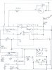
Creating bidirectional drive for just the motor/actuator could be as simple as a 12V DC power supply and a center-off, double-pole, double-throw switch, so I am puzzled about how much of the schematic you posted you want to duplicate?


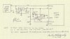
 n the green wire there is 12vdc positive/doesn't this reverse bias the diodes.Confused Bob
") ), the LED will light.
), the LED will light.