Warlord_1011
New Member
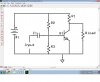
Hello all, i have set myself the task of designing from scratch at Transistor Amplifier.
I hope to be able to create an amplifier capable of providing 1 Watt into 8 Ohm from a Transistor Based amplifier.
I intend it to be based around an mp3 player, mainly because of what i have read there is a standard headphone output allowing my amp to be used on a varying array of sources (im dreaming i know)
but im having a few issues:
1) What is the source impedance, I know for example when i put my multimeter across the output of my Ipod i get 3800 Ohm (Left Channel to Ground), is this the Source/Input Impedance?
2)How do you determine what the Impedance of the actual amplifier will be once completed?
3)For a Pre-Amp stage i planed on using a BC547, now looking on the graphs i see it shows the Vce and Ib at a particular Ic at "Saturation", now how do you use these graphs to determine the BC547's Q point and how to appropriately bias the Transistor so it is not in "Cut-off" nor in "Saturation"?
BC547 Datasheet with graphs:
http://www.datasheetcatalog.org/datasheet/mcc/548B.pdf
4) Also concerning the Graphs it states the relevant values at for instance when the Ic is 10mA, or Ic is 1mA, but they only show when the Vce is 5V, how do you calculate a Vce its position relevant to the Q point to see if it is in Saturation or Cut-off?
Please help and explain as simply as possible (i struggle to make sense of things without someone talking me through it)
Many thanks and regards in advance
Last edited:
")