Continue to Site

Welcome to our site!

Electro Tech is an online community (with over 170,000 members) who enjoy talking about and building electronic circuits, projects and gadgets. To participate you need to register. Registration is free. Click here to register now.

  • Welcome to our site! Electro Tech is an online community (with over 170,000 members) who enjoy talking about and building electronic circuits, projects and gadgets. To participate you need to register. Registration is free. Click here to register now.

best way to get an op-amp put up to 5v

Status
Not open for further replies.

danrogers

Member
hi all, im working on a project which is essentially a wireless sound operated switch.

Ive had some help from audioguru and others and i've built an opamp circuit and got the wireless modules working.

The issue now is that i need to somehow use the output of the opamp to get 5v for about 0.5 seconds.

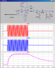
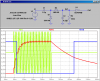
upon testing the opamp circuit with a scope, its putting out at full gain about 8-10v peak to peak (ac) but very quickly aswel. With a diode to rectify it, I get a futher drop over the diode so it ends up only peaking at about 3-4v.

now i think i have a few options to switch 5v into my ic, use a cap ( if so what kind of value) to charge when the level goes high then maybe some kind of transistor to switch the 5v to the pin. Or, use another op amp stage somehow to bring the gain up further (5v) and feed that directly into the ic.

what route do you guys think I should go down?

thanks
 
Last edited:
Using a full wave bridge rectifier will provide a higher voltage, possible enough to meet your requirements, try and see.
 
ok thanks, i will take a look at some.

what about holding the signal high for longer than the peaks, have you got any suggestions on that?

cheers
 
i havent heard of one of those? just had a little search and I'm still not sure what characteristics they have?
 
i havent heard of one of those? just had a little search and I'm still not sure what characteristics they have?

Here is an example of how to rectify a burst of signal into a level which is proportional to the amplitude of the burst. Note I'm using a "rail-to-rail output" opamp to create a signal which is 12Vpp, while the opamp is powered from 0V and 12V. (A 741 wont do that:p).

The network consisting of the two capacitors, and two diodes rectifies and filters the output with the time constants shown. Running this output into something that squares it up (Schmitt trigger gate, comparator) will turn it into a logic signal.
 

Attachments

  • D16.png
    D16.png
    35.6 KB · Views: 200
Hi Mike, that looks pretty much exactly what I need!

Im still struggling to find these rail to rail amps though, cant find anything on RS components. Are they likely to be called anything else?

I guess the output stage of your circuit after the amp would also work on my set up if I had enough gain :(

thanks!
 
I searched on DigiKey for Rail-to-Rail, 2 per 8pin DIP, operating voltage >15V, made by TI, and got this page. Can only post a snapshot.
 

Attachments

  • DKOP.png
    DKOP.png
    109.8 KB · Views: 169
cheers guys.

So you think a rail to rail amp would produce enough gain and be enough to hold that logic circuit high? it not sure how you view the gains on these things?

thanks!
 
To make a ~5V logic output, the detector circuit only needs an input of ~7Vpp, so that should unburden the opamp requirements. It doesn't matter what DC level the AC signal is riding on.

I would recommend squaring up the circuit using a Schmitt input inverter or gate to square up the signal, especially if you are counting the number of times the detector produces an output.
 

Attachments

  • E16.png
    E16.png
    30.2 KB · Views: 178
Is CD404 the schmitt inverter gate? whats the emulation software you are using there, it looks great?

In theory then, as my circuit is outputting around 8v p2p I can use it along with your output stage? or should I look into these rail to rail types?

thank you :)
 
CD4049. If you are achieving 8Vpp, then this detector will produce more than enough to trip the inverter. Search this forum for LTSpice.
 
The CD4049 is not a Schmitt trigger inverter. Use an MC14584, CD40106 or 74C14 Cmos Schmitt trigger inverter instead.

The output of your ordinary opamp is about 8V p-p and rectifying it produces a peak that is about +3.3V which might or might not trigger a Cmos Schmitt trigger inverter that has a max trigger voltage of 3.6V. If you use a rail-to-rail opamp then its peak output of +5V is reduced to +4.3V by the rectifier and the Schmitt trigger inverter will always be triggered.
 
ok thanks!

I dont suppose there is a rail to rail op amp that i can just swap out for the TL071 that i've got in the circuit at the moment is there lol?
 
There are thousands of single rail-to-rail opamps that will simply plug into your circuit instead of the TL071 opamp.
But I have never seen one and I don't know which ones are available in whichever planet you are on.
 
haha not sure what planet on im myself sometimes. but I will take a look.

so daunting though when you go look at RS website and you get 'Your search for rail to rail returned 1986 product(s) in 20 sections' lol
 
We still don't know where you are and don't know what you are talking about.
RS in the USA is RadioShack who sells overpriced surplus and maybe "seconds" electronic parts. They are gone from Canada.

RS in the UK is Radio Spares and I don't know them. Maybe they sold parts for radios 70 years ago.

There is probably a company called "RS" in every other country.
 
Status
Not open for further replies.

Latest threads

Back
Top