2camjohn
Member
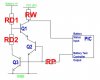
I have been using a battery indicator from Nigel Goodwins tutorials which simply divides the voltage across the battery by an amount which switches on an LED when the divided voltage drops below 0.7V
I have to modify this circuit for another application.
The important differences are:
My new circuit does not have a proper isolation switch, so I need to be able to stop the battery indicator drawing current using the software of the PIC.
My new circuit only has one LED controlled by the PIC, so I need to feed the battery information back into the PIC in order to display the battery status on the one remaining LED at the right time.
I had a go at modifying the circuit, I would appreciate any input you guys
have on it.
The idea is that the battery test controller output is used to turn on the indicator, or turn it off to save power and the battery status is fed into the battery status input of the PIC
Will it satisfy the constraints of my new circuit?
Will it work at all ???
I am going to test it, but I appreciate what you guys think.