Continue to Site

Welcome to our site!

Electro Tech is an online community (with over 170,000 members) who enjoy talking about and building electronic circuits, projects and gadgets. To participate you need to register. Registration is free. Click here to register now.

  • Welcome to our site! Electro Tech is an online community (with over 170,000 members) who enjoy talking about and building electronic circuits, projects and gadgets. To participate you need to register. Registration is free. Click here to register now.

Battery charger

Status
Not open for further replies.
Yep i have 15V, 2A power supply, so current cant be greater. But as you said, charging at 0.25C would last for a while. Maybe i should try to charge my 8Ah battery pack with 4A or even with 1C (8A), i will think about it.

Can i maybe use this current limiter? LT1084. I found it now, it is really simple and it can limit current to 3A, 5A or 7.5A. Or maybe not this one, but LM317 with 2W resistor (0.24ohm for 5A current limit)?
Or you think 2 transistors would be just fine? For transistor and LM317 version of current limiter i have everything but 2W resistors

Also notice the 'hobbyking' charger only has two 2.2 ohm power resistors
About this, i dont understand why there are 2 and not 3 shunt resistors. I understand that when all 3 are in parallel with each cell, that doesnt charge anything, but what is controlling them to shunt 3 cells?

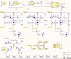
This what you posted is VERY useful. Thank you :) but again, i have some questions. http://www.zajic.cz/omezovac/omez sch.jpg
So T1 is that large transistor? Can i use P-mosfet there? And T2, R3, R4 and R5 are there only to light a led when a cell gets to 4.2V, is that true?
And in series with T1 i should put that shunt resistor?

Now to sum up, i have to put current limiter (something between 2A and 5A) to the my power supply input, and that schematic with TL431 to regulate that no cell has voltage higher than 4.20V.
Furthermore, if T2, R3, R4 and R5 are just for LEDs, i can eliminate them and use my uC to show me when my battery is full.
But what i dont get now is this: lets say my cells are 4.12V, 4.15V, 4.20V. They are charging in series, but TL431 senses that voltage on the first cell is 4.20V, so it turns T1 (or maybe mosfet) with series resistor (4.2V*0.5A=2W resistor), and then T1 dissipates 6.4W and resistor 2W, if current is 2A (but i want more). Is this correct? But how do i stop T1 and resistor from heating, and turn them off completely? But if i turn switch them off (with aditional mosfet maybe), than my 15V power supply would charge 2S battery? Would it be fine with current limiter?

Maybe i got it all right, i think i did, but if i didnt, please correct me :)
 
Last edited:
Hi,

You need LM338 for up to 5 amps, and check power dissipation.

If you found another device that goes up that high then that's ok too, but you have to check your power dissipation at the expected current and max voltage drop. The max voltage drop for 3 cells and 15v would be about:
Vdrop=15-3*3=6 volts

assuming you never let the cells get lower than 3v.
6v at 2 amps is 12 watts, which requires a decent heat sink.
6v at 3 amps is 18 watts, which requires a really good heat sink.
Etc., etc.
 
Last edited:
Yep, i just tried on the breadbord small current limiter (0.100A) circuit, and when i short its Vout and GND, voltage drop was almost 15V, and 0.100A, that is 1.5W.
Can i put maybe few just to reduce Vin voltage? With 2 diodes, voltage drop would be 1.4V, that is 13.6V, so max power dissipation would be (13.6-9)*2 amp = 9.2W.
Wow, how many problems are there...
Maybe at this point my PWM can do something about power dissipation?

I would like to understand whats "inside" my cheap hobbyking charger, and how they manage to make it with not so many components... But, true, it is only 0.8A charger. Maybe that is the reason
 
Well that is how constant current circuits work! But when you short it, you are providing a very low resistance path. Say when you shorted it it was 0.1 ohm. At 100mA, V=IR, so the voltage drop across this resistance is: 0.1 * 0.1 = 0.01V. If your power supply was 15V, then the voltage drop across the regulator would be 15-0.01 = ~15V. There is a dropout voltage across the regulator though, which determines the maximum voltage output. When you shorted it, its Vout was pretty much 0V. But if you put say a 470ohm resistor across it, it will try to force 100mA through it. Again V=IR, = 0.1 x 470 = 47V. Now you're powerign it with 15 so it can't go higher than that, but if you do this and measure Vout with respect to ground, I suspect it will be around 14V.

Also, when will you short the output? Sure the total voltage across your batteries will be 12.6V. And if charging at 2A, the load will be 12.6x2 = 25.2 watts. If you were to turn on all three shunt resistors/transistors, then they will dissipate this 25.2 watts... but balancing circuits aren't really designed to permanently shunt a battery - I believe they are meant to periodically reduce the current flowing through a cell, so it charges slower than other cells that aren't shunted. This allows those slower cells to 'catch up'.

I looks like many circuits don't actually 'balance'. They simply charge all three cells with constant current, then shunt regulate the voltage across any cell that has reached its target voltage (4.2V). So really, it just 'turns off' charging of a cell once it has been charged. I believe your hobbyking charger only had two shunt resistors because it works in a similar way. That is, as each cell reaches 4.2V, the resistor is switched across it. But once two cells have been charged, it only needs to wait for the last cell to charge.. once this reaches 4.2V, no need to shunt it with a resistor, because all three cells are done! So for that charger you need cells-1 number of shunting circuits.

The downside of this is power dissipation. I suspect the hobbyking charger doesn't use a very high charging current, probably <1A. The resistors aren't big enough to dissipate more than 3-4 watts. For reasonable charging times (7 hours, over night) you will indeed need 2A+, doubling the dissipation, making resistors significantly larger, and requiring larger heatsinks on transistors :)

I would use a shunt circuit for each cell, with a higher value resistor, so it steals less current from the charging battery. And your micro should periodically check the voltages of each cell, and turn on the shunt periodically for the cell with the highest voltage.
It's mean to 'balance' things out, constantly adjusting the charging currents to keep them all, more or less the same.

I got the impression you hadn't thought too much about power dissipation. When dealing with currents of >1A, every volt across a device, will dissipate over a watt. A TO-220 package, without a heatsink, can dissipate, at most, around 2W. For resistors, if you have a 2.2ohm resistor across a cell, that is used to shunt charging current, the current is 2A, voltage is 4.2 = 8.4watts. A 10W resistor would get extremely hot if this was switched on for any length of time.

I have never deisgned a balancing charger, and frankly don't know much about them, I'm just guessing here, and saying what *I* would do in that situation.
 
Also, when will you short the output?
Never :) i have just never tested LM338 as a current limiter, so now i did it and it worked like it should. Limited current depends on resistor and that value can be calculated

You said i would need 2 shount resistors for 3 cell battery. Ok, but what if i have shunt for cell 1 and cell 2, and not for cell 3. And voltages are 4.00V, 4.00V, 4.15V. Cell 3 will very soon be charged to 4.20V (while others are not), and it cant be shunted, thats why i dont understand it. If cell without a shunt is the last one that reaches 4.20V, than ok

I dont understan why, if you put a 2 ohm shunt resistor across a cell, power dissipation would be 2*4.2=8.4W? I would say the current will flow from battery trohugh shunt resistor back to battery. So U=IR, I=U/R=4.2/2.....P=2.1W?

Based on this schematics (http://www.zajic.cz/omezovac/omez sch.jpg) you have posted to me, i have designed a completely new charging circuit. There is no uC on this screenshot, but now it only measures current, sends PWM to charge pin on schematic, and measure voltage on every cell. Once the charging is finished, it will turn off Q7 and everything is turned off. So now i have PWM to lower the charging voltage (lets say from 15V to 10V for empty battery), but if that fails, Current limiter would regulate this, and dissipate energy as a heat.

What do you say about this schematics? I put values on every (shunt) resistor, and you can see my current limit

EDIT: maybe i understand now. I could do it this way: "listen" if any cell is beeing shunted (voltage is 4.20 or greater), and if it is, that cell is discharging with 2A of current, and charger is OFF at that moment. Then, when no cells are beeing shunded, charging can resume.
When charger is ON again, it will charge all 3 cells again, one of them will soon be at 4.20V, but others voltages will raise to.
Tell me if i got it all wrong :)
 

Attachments

  • charger6.JPG
    charger6.JPG
    158.1 KB · Views: 935
Last edited:
Hello again,

Lets not forget that we are working on the assumption that the charger is to be a very simple design, which imposes certain restrictions. An optimum charger would switch OUT every cell as it became charged, and rather than use a linear current regulator it would use a buck type current mode switching regulator. This kind of regulator would keep power dissipation to a minimum as the cell positions where actually completely shorted, not replaced by resistors.

Also, you have to calculate two different voltage limits:
A. The lower limit which could be around 3*3=9v
B. The upper limit which will be exactly 3*4.2=12.6v

The upper limit comes into play when you use a linear current regulator because there has to be enough overhead voltage for it to work properly. With a supply of 15v that leaves:
15-12.6=2.4v

which probably isnt enough overhead for a regular linear regulator. If i remember right, the linear regulator will need 2.5v plus any output, which for a current limiter would be 1.25v, which brings the total to 2.5+1.25=3.75v overhead. This means we would need a voltage supply of:
12.60+3.75=16.35 volts.
but you should double check this figure with a simulator at least, or check the data sheet to make sure i have that right.

As i was saying above, an optimum charger would probably switch out each cell as it becomes charged and replace it with a short circuit, using a switch mode current mode regulator instead of a linear. The switch mode regulator would have an inductor to convert power rather than just limit current itself.
 
Ok, i found that LM2576 (that i already have) can limit current to 3A, using switching mode.
I understand those voltage drops, and i would see if this regulator fits my application.

What i dont understand is the way how to switch out a fully charged cell? They are charging in series, and how do i switch anything out then? :/
 
Hello again,

Well i assumed you would use a MOSFET in series with the cell rather than in parallel, but have another in parallel to switch once the first MOSFET opens up. You'd have to figure out the drive arrangement and make sure the bias and drive is right etc. before and after the switch activation.
 
If you were to completely switch out cells, you could do this using MOSFETs, two at the two 'middle' nodes, and a single MOSFET at the top and bottom = 6 MOSFET's. As the cells are permanently connected in series, you can't just just disconnect two cells, but you can control where you apply power, and GND. It can get very complicated knowing the combinations.. especially as the high-sides (switching to the power rail) will be Pmos, the low sides will be Nmos (switching to gnd). Perhaps I am over complicating it (I often do that..) . Also, for power dissipation, you may need to switch in resistors.

Using a switching regulator can (but not always!) be more efficient. It does however, bring its own problems... It will need to be constant current regulation, which involves measuring current - usually a current sense resistor - on the low side. Low side current measurement adds voltage to ground, meaning your voltage measurements of the cells are no longer referenced to ground. Example: 0.2Ohm sense resistor, for a charge current of 2A. If this is a low side resistor, it will develop 0.4V across it. Now this connects to the first cell in the series, which is say, 3.9V. If your micro is referenced to ground, it will measure that cells voltage as 4.3V. (3.9 + 0.4). For this reason, 'high-side' current measurement is used, which is more difficult to implement accurately (but we don't really need accuracy!). A great advantage of the switching reg is efficiency with large Vin-Vout difference. Example:

Say your input is 15V. You are charging at 2A, 3 cells in a pack , maybe 3.7V, 3.8V and 3.6V. That's a total of 11.1V. A linear reg would dissipate P = IV, = 2 x (15-11.1) = 2 x 3.9 = 7.8W. Efficiency isn't too bad, (30 - 7.8)/30W = 74%.
But as you charge, what if one cell reaches 4.2V long before the others? If we were to 'switch this out', without replacing the cells load with a resistor, we just have two cells in series, both at say 4.1V. Now we have our regulator with 15V in, but 8.2V out (2 x 4.1V). So our poor regulator has 15-8.2 = 6.8V across it. At 2A thats 13.6W. A switching regulator would keep its efficiency rather high, but draw less current from the input = less power dissipation, smaller heatsinks!


First port of call, make a nice switched-mode constant current supply :)

Side note:
Of course, MrAl, myself, and you are all making the assumption that the cells are all charged at the same current/rate, and that we just blast them with constant current, and once they are at 4.2V we 'switch it out'. That is a brute force approach, a bit like charging one cell at a time. And in a way is fool proof, but it isn't really balancing.. However, even when in series, you can control the charge current for each individual cell by switching in a resistor in parallel. This allows you to have say cells 1 and 3 charge at the max current (we'll assume you're using a 2A constant current reg) - but cell 2 can have a 10ohm resistor resistor in parallel with it. If the cell is say 3.8V, the voltage across the resistor will be 3.8V, and so I = V/R = 3.8/10 - 380mA will flow through it. 2A will flow through the resistor/cell parallel combination, so the cell now only gets 2-0.38 = 1.62A. It will charge at a slower rate (but also, its voltage will drop as the charge current will drop). You can periodically, say for 2 seconds, every 2 seconds, switch in that resistor if the cells voltage (when all shunt resistors are off) is higher than the others.
 
Hi,

I dont believe balancing is as important in the three cell pack, even though it is desirable. In the parallel pack i believe it is more important when charging the cells individually because even a small voltage difference can cause a high current between cells when they are finally connected back in parallel. I have one flashlight that takes four Li-ion cells in parallel so i have to watch this myself. I only use it with two cells though (it runs with two to four cells) so i have to balance two cells before using them in the light.
In series the main issue i think is that one cell might run down before the others, but that means that the capacities all have to be the same or close to the same, and that is harder to guarantee. A monitor on each cell would help here.
 
I vaguely remembered an EDN design idea for using a buck with a dual opamp for a straight forward constant current supply.. and found it, someone had posted it in this very forum..

https://www.electro-tech-online.com/attachments/edn-switch-constant-current-png.13319/

Might look more complicated that you're after, and there are one-chip solutions, but switching CC chargers often have a high part count than their linear counterparts.

In order to limit output voltage (not true regulation, just stop it from going about say, 13V..) a simple trick would be a zener diode from Vout to the feedback pin, along with a ~10k resistor from the feedback pin to ground. Zeners cathode to Vout, and anode to the feedback pin. The opamps output will need a small diode on its output. A 12V zener, will probably start to conduct at ~11.75V. the Feedback pin's Vref is 1.25V, so once the output goes above 11.75+1.25 = 13V, it regulates.

Easier option would be one of these:
**broken link removed**

You'll have to manually set the trimpots for maximum charge current (using a power resistor as a load) and the maximum output voltage (just a multimeter), but once that is done, you can leave it. It uses low side current measurement so your cells and circuitry's ground should be connected to 'Vout-' on this. The 5V regulator for the micro can be powered from your 15V input though.
 
Last edited:
Status
Not open for further replies.

New Articles From Microcontroller Tips

Back
Top