I am working on building an electronic baseball pitching target that will record the location the ball passes through an array of laser emitters/photo sensors (16 sensors high, 11 sensors wide). Sensors will be spaced at 2 13/16" (2.81") which is just smaller than a standard baseball so that a ball cannot pass through the matrix without tripping at least 1 horizontal AND 1 vertical sensor. Since the spacing is smaller than a baseball, it is possible that a ball may interrupt up to 4 beams (2 horiz and 2 vert). And with the quickly tested thickness of the beams, it is more than likely that more than one beam per axis will be interrupted per pitch. I need to do more testing there.
At this moment, I am only concerned about getting an X and Y "signal" to the Arduino to "let" it figure out balls, strikes, etc., and whatever outputs I decide to use. Once I feel confident about being able to detect and determine a pitch location, then I will move forward with what to do with that information.
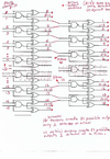
I have designed a circuit which I THINK") will ensure that only 1 "output" line goes high for each of the 2 matrix axes. It uses a NAND gate and 2 XOR gates for each "pair" of adjacent sensors. The possible outputs (ONLY 1 at a time) are: neither was tripped, sensor A was tripped, Sensor B was tripped OR they were BOTH tripped. B is then compared with C, C with D, etc., thru all the sensors, both horizontal and vertical (but separate circuits for each axis). With 16 horizontal sensors, there are 31 possible conditions - with only one being allowed to pass thru the logic for processing to input to the Arduino. With 11 vertical sensors, there are 21 possible conditions - with, again, only 1 being processed to make it to the Arduino inputs.
will ensure that only 1 "output" line goes high for each of the 2 matrix axes. It uses a NAND gate and 2 XOR gates for each "pair" of adjacent sensors. The possible outputs (ONLY 1 at a time) are: neither was tripped, sensor A was tripped, Sensor B was tripped OR they were BOTH tripped. B is then compared with C, C with D, etc., thru all the sensors, both horizontal and vertical (but separate circuits for each axis). With 16 horizontal sensors, there are 31 possible conditions - with only one being allowed to pass thru the logic for processing to input to the Arduino. With 11 vertical sensors, there are 21 possible conditions - with, again, only 1 being processed to make it to the Arduino inputs.
I could have used priority encoders and selected which would have priority if two adjacent beams are interrupted, but I wanted to try it without that which could display the pitch in the wrong spot. Though - it really needn't be this precise but that is my goal at the moment.
The attached file is what I have come up with to "ensure" that only one of the possible 21 vertical conditions goes active, and one of the 31 possible horizontal conditions goes active for each pitch. I did not show the comparison circuits for every sensor, it's all very repetetive. I also only showed a representation of the 16 horizontal sensors. The vertical sensors are connected exactly the same way but there are only 11 sensors.
The 31 horizontal outputs will be fed to a circuit to convert from those 31 lines to 5 binary lines to input to the Arduino.
The 21 vertical outputs will be converted to 5 binary lines for input to the Arduino. The program will determine the spot the pitch came though the target using those two coordinates.
Basically, each of the 31 (and separately, the 21) will be fed to the proper 8 input OR gates to end up with it's associated binary number (output #15 will encode to 01111, output #3 to 00011, etc.) I haven't drawn it up yet but I have completed a table to determine which binary digits each output needs to be wired to. With 31 possibilities, I think it worked out to requiring 2 8 input OR gates, each of which would be fed to a 2 input OR gate -- for each of the 5 binary digits.
What I'm looking for here - does the attached circuit seem like it will work to ensure that for any given pitch, only 1 data line goes HIGH out of the horizontal, and only one goes HIGH out of the vertical circuit?? Is what I described (but haven't drawn yet) sound like a reasonable way to encode from 31 lines to a 5 digit binary number (and from 21 lines to a 5 digit binary)??
Also, if any of this looks good on paper, I'm wondering if I should add a resettable latch to each of the photo sensor lines to lock the state of the pitch while everything has time to process. Just feed the photo sensor output to a latch and once the calculations for a pitch are done, let the Arduino reset the latches...
Any help, comments, etc., would be most appreciated...
At this moment, I am only concerned about getting an X and Y "signal" to the Arduino to "let" it figure out balls, strikes, etc., and whatever outputs I decide to use. Once I feel confident about being able to detect and determine a pitch location, then I will move forward with what to do with that information.
I have designed a circuit which I THINK
will ensure that only 1 "output" line goes high for each of the 2 matrix axes. It uses a NAND gate and 2 XOR gates for each "pair" of adjacent sensors. The possible outputs (ONLY 1 at a time) are: neither was tripped, sensor A was tripped, Sensor B was tripped OR they were BOTH tripped. B is then compared with C, C with D, etc., thru all the sensors, both horizontal and vertical (but separate circuits for each axis). With 16 horizontal sensors, there are 31 possible conditions - with only one being allowed to pass thru the logic for processing to input to the Arduino. With 11 vertical sensors, there are 21 possible conditions - with, again, only 1 being processed to make it to the Arduino inputs.I could have used priority encoders and selected which would have priority if two adjacent beams are interrupted, but I wanted to try it without that which could display the pitch in the wrong spot. Though - it really needn't be this precise but that is my goal at the moment.
The attached file is what I have come up with to "ensure" that only one of the possible 21 vertical conditions goes active, and one of the 31 possible horizontal conditions goes active for each pitch. I did not show the comparison circuits for every sensor, it's all very repetetive. I also only showed a representation of the 16 horizontal sensors. The vertical sensors are connected exactly the same way but there are only 11 sensors.
The 31 horizontal outputs will be fed to a circuit to convert from those 31 lines to 5 binary lines to input to the Arduino.
The 21 vertical outputs will be converted to 5 binary lines for input to the Arduino. The program will determine the spot the pitch came though the target using those two coordinates.
Basically, each of the 31 (and separately, the 21) will be fed to the proper 8 input OR gates to end up with it's associated binary number (output #15 will encode to 01111, output #3 to 00011, etc.) I haven't drawn it up yet but I have completed a table to determine which binary digits each output needs to be wired to. With 31 possibilities, I think it worked out to requiring 2 8 input OR gates, each of which would be fed to a 2 input OR gate -- for each of the 5 binary digits.
What I'm looking for here - does the attached circuit seem like it will work to ensure that for any given pitch, only 1 data line goes HIGH out of the horizontal, and only one goes HIGH out of the vertical circuit?? Is what I described (but haven't drawn yet) sound like a reasonable way to encode from 31 lines to a 5 digit binary number (and from 21 lines to a 5 digit binary)??
Also, if any of this looks good on paper, I'm wondering if I should add a resettable latch to each of the photo sensor lines to lock the state of the pitch while everything has time to process. Just feed the photo sensor output to a latch and once the calculations for a pitch are done, let the Arduino reset the latches...
Any help, comments, etc., would be most appreciated...
Attachments
Last edited:
