Continue to Site

Welcome to our site!

Electro Tech is an online community (with over 170,000 members) who enjoy talking about and building electronic circuits, projects and gadgets. To participate you need to register. Registration is free. Click here to register now.

  • Welcome to our site! Electro Tech is an online community (with over 170,000 members) who enjoy talking about and building electronic circuits, projects and gadgets. To participate you need to register. Registration is free. Click here to register now.

Bad LED Datasheet

Status
Not open for further replies.

AtomSoft

Well-Known Member
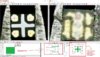
Okay i realized i had these cool tiny leds but they never worked. Am i going crazy or does this :LED have the pins reversed in datasheet?
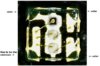
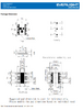
the 2 images on top half show the actual LED under a microscope... the image on bottom is from their datasheet.

Forgot to say actual PART:

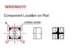
If you look close it looks like what i labeld PIN 2 to actually be PIN 1 or COMMON ANODE. since it s a long bar and all leds connect to this one.
 

Attachments

  • led2.jpg
    led2.jpg
    9.1 KB · Views: 228
  • led.um.jpg
    led.um.jpg
    343 KB · Views: 224
Last edited:
Going to send a test PCB to get made from OSHPark. It will allow me to test every pin and include resistors. This will allow me to determine which pin is which and use a microscope easily.
 

Attachments

  • test_pcb.jpg
    test_pcb.jpg
    175 KB · Views: 210
i wet the led with alcohol... and way better image.. pin 2 has to be common... hopefully anode
 

Attachments

  • new_pins.jpg
    new_pins.jpg
    62.4 KB · Views: 218
I agree, that has to be the common. Could it be that you've misidentified pin 1?

Mike.
 
Ok tested the LED with wires.. im way to impatient lol Here is the correct pinout:
 

Attachments

  • LRTBR48G.jpg
    LRTBR48G.jpg
    99.9 KB · Views: 210
  • LRTBR48G.pdf
    153.3 KB · Views: 249
I agree, that has to be the common. Could it be that you've misidentified pin 1?

Mike.
I doubt it. that image named: led.um.jpg

Is me holding it with a TWEEZER. Never letting go and rotating my hand to take a front and back shot. Hence all pins flipped horizontally. I would have to have flipped it vertically and horizontally to get it wrong i think. Check out the image above, I tested it and labeled them . Even made a small datasheet
 
Ok after all of that i figured a simple reason why this was bad. I dont know if its only my parts but R is labeled PIN 1 on my parts. The actual WHITE marker is wrong. If you rotate it all the pins line up. So my parts must be marked wrong.

Sucks cause these are NOT FAKES> from MOUSER ... directly. so... idk
 
Sucks cause these are NOT FAKES> from MOUSER ... directly. so... idk

That's no guarantee they aren't fakes, Mouser presumably buy them from China?, so fakes could easily be sneaked in over there.

Obviously you've much more chance of them NOT been fakes, but it's certainly easily possible.
 
I'm new to both this forum and electronics and one thing I've noticed about some data sheets is they are like engeneering blueprints sometimes the part is oriented on paper in such a way that your looking through it like it's transparent
 
I'm new to both this forum and electronics and one thing I've noticed about some data sheets is they are like engeneering blueprints sometimes the part is oriented on paper in such a way that your looking through it like it's transparent
Yeah that's true. But the datasheet shows an image of the led on a pad with common anode on the right top side meaning the next image must be flipped since it's on top left.

They clearly mark the package pin 1 .. as common anode.. but same exact pin which is the marked one on my package is RED cathode.. so not a mixup by me.. but who ever made em.

It's ok tho. I stopped using them and decided on a new RGB led.
 

Attachments

  • Screenshot_20200429-205359~2.png
    Screenshot_20200429-205359~2.png
    289.8 KB · Views: 219
Status
Not open for further replies.

Latest threads

New Articles From Microcontroller Tips

Back
Top