Continue to Site

Welcome to our site!

Electro Tech is an online community (with over 170,000 members) who enjoy talking about and building electronic circuits, projects and gadgets. To participate you need to register. Registration is free. Click here to register now.

  • Welcome to our site! Electro Tech is an online community (with over 170,000 members) who enjoy talking about and building electronic circuits, projects and gadgets. To participate you need to register. Registration is free. Click here to register now.

Automotive 6 Volt Generator Transistor Voltage Regulator

Status
Not open for further replies.
Backwards on the output side. So, opening the MOSFET "disables" the gen field. Thanks for the update.

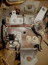
Yes, I didn't have any 50 ohm resistors. So, the 47ohms had to replace. I should have labeled the picture with the functions. Everything runs linearly right to left except the MP350 output which runs to the IRF540 on the base. I tried to keep everything inside the sealed cap to keep it dry. Hope it doesn't make the MOSFET and the 80A rectifier run hotter.

IMG_1748.JPG
 
Probably be ok, the MOSFET's Don't get hot unless they are 1/2 way on. The Cutout Diode will get very hot with the headlights on but if it's mounted against the metal with a heat sink insulator it would track a few degrees over Generator Temperature, I have seen mine hit 250'F and still work fine. I think the The 82CNQ030 center tap Schottky rectifier module Cutout Diodes have a 150' C rating It will need to dissipate about 15 watts. IR 82CNQ030.
P.S. You can find them on e-bay for about $5 each plus shipping.
 
Last edited:
Danwvw Dan. You developed a pretty good following for this "bumpy" ride of yours. Your schematics remind me of the Radio Shack ones. They don;t have cartoons like Tektronix does and there aren't any Easter Eggs. e.g. When you take the regulator apart, there it is, "a schematic" inside.
 
Good Idea! Here are photos of the working 350e prototype 2 that I put back in the car after the 350e (1) failed due to the 6.8 V Zener blew. This regulator seems to be bullet Proof! I always revert back to a 350e when something doesn't work. Note! this one 350e (2) has a 2.5m ohm Trench Power MOSFET: FDP025N06 and it seems to deliver the best charge voltage at Idle 3 or 4 Tenths better, over a MTP75N03HDL FET.
finalized-prototype-350-jpeg.130711

finalized-prototype-350-bottom_2-jpeg.130712
 
Last edited:
The 350e (1) with the Large 9mm VW spade lugs is back on the car and working perfectly after changing the 6.8v Zener Diode. (Note! this is an updated prototype with a 820uf Cap on D+ to ground which seems to have a stabilizing influence). UpDated Schematic and note to myself use this link to add media!
Regulator 350e(1).jpeg
 
Last edited:
Added 2 0.4F @4.5 VDC SuperCapacitors in series to the power at the ignition switched 6 volt where the Alarm Circuit is and it worked nicely to eliminate the noise which was like little crackling sounds the alarm circuit was making. in the 6.8 to 7,2 volt range. Note the car does not shutoff for about 1 second now when the key is turned off. The voltage reading however are a little higher. Just wondering though. Would it be better for the SuperCapacitor if it were on the Un-Switched side of the ignitions switch? It would then stay on all the time but may be harder on the Ignition Switch? Also just wondering, do SuperCapacitor's ever catch fire?
View attachment 121766

View attachment 121767
Alarm Circuit installed November 2019:
The Alarm Circuit has proven it's self and saved overcharging several times with the various failures including the last one caused by a failure of the 6.8 Volt Voltage Reference diode. There have been Zero problems since with anything.
Hi Dan,
supercaps can fail from overvoltage, I don't know if they can catch fire.
Possibly a 1A fuse may be an idea, just in case?

With two or more in series, add equalising resistors across them to ensure the voltage across either one does not creep up over time if the leakage is different between the two.
That should hopefully avoid any problems.
It's Been over 2 Years Now:
It's good that I revisited your comment "rjenkinsgb:" As I never fused this separately from the VW's fuse if I even have it on the fuse side of the fuse block, I need to check. It should be and be on the instrument circuit, I will check this. One thing is it's located just behind the dash where if the supercapacitor did short out it would smoke things up and smell and be quickly noticed. One thing that is good is that the supercapacitor chosen for this application worked out very nicely and is still performing flawlessly without resistors.
 
Last edited:
Danwvw, have you seen Dr. Hugo Holden's work before? You might be interested in
THE TRUE RB106 EMULATOR:
SIMPLE DYNAMO REGULATOR MK2c
"This article describes an all electronic modification or upgrade to the Lucas RB106 Dynamo regulator into a fully electronic unit which emulates the electrical properties of the original Lucas RB106." He seems to do a very thorough job. I found it worth reading even though I wouldn't use his design. I've also been wishing for something like his
#THE RB106 TEST MACHINE. I just stumbled across this while trying to learn more about "inductive kick".
 
Interesting the input to the Comparator input configuration in his Fig 2 is Just how I finally arived at as a simple configuration, Some Comparators can't handle it though!
 
Fewer parts could be used if the LM311 is subbed by a UA723 with built-in voltage reference, and can also drive a MOSFET.
 
This thread is very interesting. I am not an electrical genius so please forgive me. I have been having trouble with my charging system. I have a '47 Plymouth that uses an Auto-Lite, 6 volt, positive ground, and 35 amp. generator. The regulator is an Auto-Lite unit rated for 35-45 amp. What would need to be changed to get this to work in my application?
 
I think it would be best to stick with the original Auto-LiteThe VRR4005A on the Positive Ground Systems. about $60 on ebay. Perhaps https://cloversystems.designscience.info/products/legacy-products/dr340/ has something.
Danwvw Thank you for responding!

I am currently using a Standard Ignition VR-2 regulator which is a modern replacement unit. I believe the contacts are sticking in the replacement regulator. Sometimes it charges, and most of the times it does not. I do have an original Auto-Lite VRP-4401A for this application as my next step in troubleshooting. As I was told the modern replacement regulators do not have enough silver on the contacts to prevent sticking. I was just hoping to eliminate the contact points all together so this would not happen again.

I looked into Clover Systems soon as I started having problems but they went out of business in 2017.

I am very appreciative and thank you for your suggestion!
 
August 2022 UpDate, The 350e prototype1 updated design on the regulator housing with the 9mm spade lugs has been fine on the car for a year now however the other day I went driving back up in the mountains on some logging roads and was running with the headlights on and climbing in 1st gear for about 1/2 an hour and when we stopped for a break I noticed the Gen lite glowing a bit with the key off. This is a sign of the Barrier Diode conducting backward, It worked fine going back home with the lights mostly off.
Later took the car out and the Regulator went to full charge putting out over 9 volts then quit charging.
Troubleshooting reveled the STPS80L Barrier Diode was shorted out as well as the 75N03HD MOSFET.
Now running the 350e Prototype2 board on the original regulator with the B+ wire clamp screw instead of the 9mm spade lugs.
 

Attachments

  • 350Prototype2Bottom.jpeg
    350Prototype2Bottom.jpeg
    421.6 KB · Views: 197
Last edited:
Status
Not open for further replies.

Latest threads

New Articles From Microcontroller Tips

Back
Top