Continue to Site

Welcome to our site!

Electro Tech is an online community (with over 170,000 members) who enjoy talking about and building electronic circuits, projects and gadgets. To participate you need to register. Registration is free. Click here to register now.

  • Welcome to our site! Electro Tech is an online community (with over 170,000 members) who enjoy talking about and building electronic circuits, projects and gadgets. To participate you need to register. Registration is free. Click here to register now.

Automotive 6 Volt Generator Transistor Voltage Regulator

Status
Not open for further replies.
Hi Danwvw I am ordering some parts. I am still thinking that your circuit feb 12th 2021 met my alternator 6v dc. Some background the mechanic regulator has 3 functions a voltage regulator , a current regulator and a counter current regulator. Mass is car chassis, 6v DC alternator .
Great to see the pictures, Yes everything should work fine!
Citron.jpg


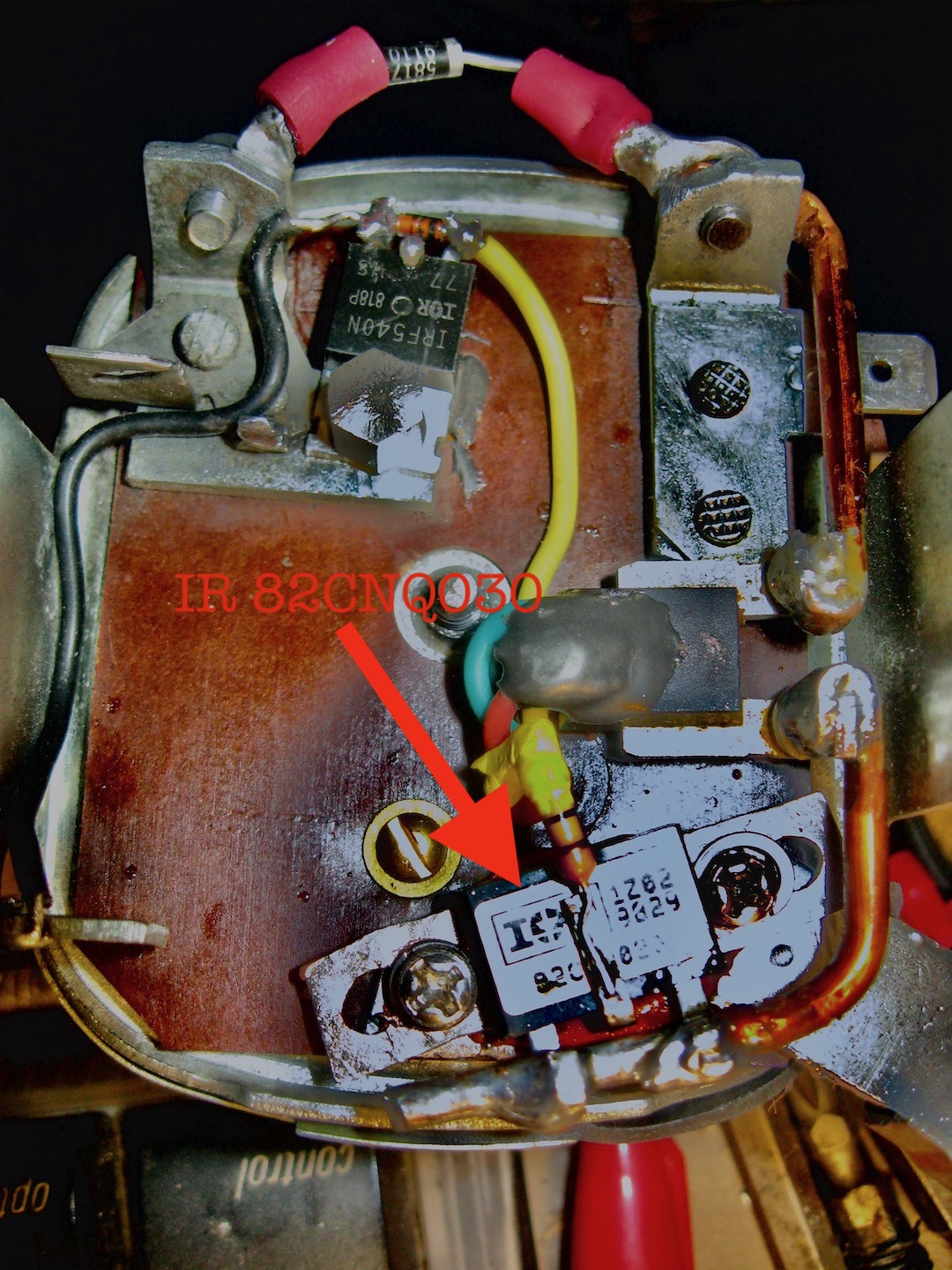
Wires like this: Hook up both D+ legs of the cutout diode to the Dynamo: I did this on the bottom of my old mechanical regulator with the cutout diodes common cathode connection to the battery made by it's case clamped against the B+ bus on the old regulator Here: Bottom View .
pcb41.JPG
 
Last edited:
Link didn't work directly, but found it. It's amazing how technology changes. This was designed specifically for the alternator/motor combination. The alternator, I guess, could be considered a 3 phase motor?
 
The alternator, I guess, could be considered a 3 phase motor?

Yeah, in the motors for bicycles and such, they either replace the field winding(rotor) with permanent magnets or power them with the battery, then use a BLDC motor controller. I checked again and the link opens right up using Firefox.
 
Currently I am running the Prototype 393i (1) with the IR 82CNQ030 Rectifier Diode for the Cutout Diode that may solve a saturation problem I experienced with the 80X15 Oring diodes. Lowered the value of the 10 ohm resistor to 3 ohms for the 3 Volt reference which raised it to 3.1 volts and this is helping with better voltage with the headlights on.
Bottom View Prototype 393i (1) showing the IR cutout diode installed:
Also I have built a second 325i (2) Prototype with some changes: (The 393 input pins are all now on the green terminal blocks)
393i (2) Schematic:
Schematic 393i (2) May 17 Update.jpeg


And the Circuit Board Layout is much nicer, 393i (2) Top View:
Photrotype 395i (2).jpeg
 
Last edited:
Today I think I may have figured out the problem with the LT-6700-1 Designs. In an attempt to rebuild the Voltage only LT-6700-1 Chip Prototype I discovered that High Frequency Oscillations were Negating the circuits ability to accurately sample it's own internal 0.4 Volt Voltage Reference.
After completely reconstructing the prototype and thoroughly testing it's thresholds I discovered a 0.1uf filter capacitor closely mounted to the LT-6700's VS pin 5 was needed to prevent High Frequency Oscillations that were defeating its ability to accurately reference it's own 0.4 volt internal voltage reference.
In this photo bench testing with the Bench Gen the Fluke Multimeter is measuring across the -in pin 4 to ground and reading over flow through the 6.8 Volt Zener Diode, The Red Display is displaying 6.95 Volts or so is the B+ output of this particular design. However my digital flash filled in the blanks making it appear as 8.8.8. The Scope is measuring the MOSFET output at where it would connect to the Field wire of a generator. It's showing almost 8 Volts P-P With 2.31481 cm X 1ms or 432 Hz:
Designs The LT-6700.jpeg
 
Last edited:
The LT-6700 when installed on the car didn't work! Stuck ON: (MayBe a Blown IC) Even with the above modifications it is overcharging. The 393i #2 has some problem too. "Intermittent Over charging" I think it was just a loose resistor connection at the TB.
 
Last edited:
Danwvw,

Wow, excellent work on the voltage regulator designs. I, like you, have a 6V 1960 Beetle and am thinking about trying your ADCMP350 design.

Is it still the case that the February 16, 2021 update with the safety resistor and the B+ diodes is the latest? Can I use the STPS40L15 diodes for my 7V/45A generator or should I stick with your STPS80L15 diodes?

FYI, in addition to your eBay source for the SC-70/SOT-343 prototype boards I have found an Amazon provider in this link SOT-343 prototype board.
 
The 350 design is a good way to go. I still like the 8 pin DIP chip designs like the LM-393 for being easy to hand solder and easy to replace the chip on because they're not tiny SMT "Surface Mount Technology" however I don't have the 393 design bugs completely worked out.
Either the 40 amp or the 80 amp cutout diodes work good with one exception where a 40 amp diode would lock on when hot after the car was turned off but I upgraded to a better part the IR 82CNQ030 **broken link removed** center tap Schottky rectifier. It has very little reverse current leakage and 0.37 Volts drop at 40 amps meaning it will need to dissipate 15 watts of heat into the B+ output bus. In the 60 beetle it's going to get up to 65c there on the regulator easy in the summer. Probably adding the Schottky diode there is asking for a problem if you live where it gets hot. The IR 82CNQ030 can operate up as high as 150c though and tested very nicely but engine temperatures were fairly cool during the testing. Yes the Feb 16 update Schematic is still up to date. https://www.electro-tech-online.com...or.157408/page-21#lg=attachment130710&slide=0
 
Last edited:
I've got all of the pieces I need on order. So, should be fabricating next week.

Those 82CNQ30 Schottky's were pricey on Mouser and Digikey at $20. Glad I found the eBay ad for the International Rectifier brand for $6 shipped.

Yes, the SC-70 package is tiny, but will give me a chance to try out the reflow oven I built recently. Plus, there should be no chance of the IC working loose due to heating & cooling or vibrations like could possibly happen with dip packages.

If you are interested in the reflow oven project, I followed this design utilizing the Panasonic toaster oven and Tiny PID Controller. It cost about me $150 and a couple of hours time.
 
Last edited:
I used break out boards and just Lead Solder and a Soldering Iron Just hit it with a bit of heat and solder and a 1/16" chisel soldering tip and drag it away from the chip, takes a couple of tries to get all the pins soldered. Solder past would be nice! Post a Photo when you have something going!
 
Installed the 393i Prototype 2 in the car and have been testing. It was over charging slightly up to 7.5volts at the battery, Found a possible Short on the 100K resistor feedback. Needs further testing. Did some current testing etc.. It seems to be working now as it should. Note the differences between 395i Prototype 1 in Purple and 395i Prototype 2 circled in Red.
Schematic_393_1_2.jpeg
 
I figured out what was causing the over charging on 395i Prototype 2. The 100 K feed back was causing the reference voltage to rise and the 0.1 uf cap was making the overcharging worse. I did more testing it charges the battery pretty good with the lights on and the battery down. Current limit holds the charge voltage down to as low as 6.1 volts after a 1/2 hower discharge with the headlights left on. I will recharge even with the lights on slowly the voltage goes up at the battery to about 6.8 lights on 7.05 volts lights off. It seems to hold 7.00 to 7.100 volts now fully charged lights off.
Here is the Updated Schematic:
Schematic 395i # 2.jpeg
 
Last edited:
Danwvw,

Am I mistaken that for your ADCMP350 design the input voltage at pin 1 should be approximately 6.8V with the 6.8V zener diode and approximately 7.5V with the 7.5V zener? I have followed your schematic, but am getting roughly 1.25V and 1.5V respectively for the 6.8 and 7.5V zeners. Should the zener not be directly tied to ground with the 330ohm resistor just before it and then taking the junction of resistor/zener to pin 1 of the MP350? This would be similar to what you have done for the 4.7V VCC on pin 4.

On another note, is there any other connection between the F terminal and the D+ terminal other than the 1N5817 diode?

Finally, I have found your regulator test circuit on page 18 of this thread. A couple of questions. First, are you using a 12V car or motorcycle battery for the power source? Finally, what wattage are the resistors (2W?) and what voltage for the capacitor (16V?)?

Thank you!
 
Last edited:
"60 Beetle" No, When the voltage regulator becomes operational the voltage at Pin 1 will regulate at the threshold voltage of the internal reference inside the ADCMP350 IC which is 0.60 Volts DC. What should happen is the generator output will continue to rise until some current begins to build voltage across the 330 ohm resistor to ground because the generator is putting out more voltage than the 6.8 volts it takes to avalanche over the Zener diode. When pin1 hits the threshold voltage 0.60 volts the IC shuts off the Power Mosfet, this continues to happen on and off very quickly and it establishes the Voltage the Generator gets regulated at which will be 6.8+0.6 volts.
No "F" the field just connects to the Diode to D+ (which is there to suppress voltage spikes and to cancel unwanted EMF on the field of the generator this makes the generator operate more efficiently) and "F" also connects to the Drain of the Power Mosfet, but the Field resistor like in the mechanical regulator is eliminated.

A 12 volt motorcycle battery would work fine to power a generator Simulator circuit, I used 3 Rechargeable 18650 Lithium Ion batteries in series. As far as capacitor Voltage anything over 12 volts would be fine and as far as wattage on the resistors I think I did it with 2 watt 100 ohm load resistors and a 5 watt 5.6 ohm but that was probably overkill. If your test load is not much the wattages can be lower. Other resistors like the 15 ohm and other input 100 and 200 ohm could be 1/4 watt.

Schematic 350 update.jpeg

Schematic Generator Simulator (1).jpeg
 
Last edited:
Danwvw,

Thank you for the quick reply. As you may have deduced, I am a complete amateur/novice in electronics. I have been attempting to self-learn since retiring 4 years ago. So, I spent the entire weekend reading/researching to understand the logic of your design and the devices utilized. Here is what I believe is occurring using a 6.8volt Zener diode and an IRF540 Mosfet. If I am mistaken, please advise.

On the #1 pin to the ADCMP350 the circuit is “open” until a 0.6 volt increase in voltage has been realized. This process is started when the voltage from the generator reaches 6.8v +/-5% (my diode is rated at 5%) and thus current starts to flow due to the 330ohm resistor to ground. At this point up until 7.4v +/-5% the circuit is still “open”. Voltage above 7.4v +/- the MP350 “closes” the circuit and opens the output by closing the internal Mosfet.

At the output, we have a 4.7K pull-up resistor which keeps the internal Mosfet in the MP350 in the open state. The 1N4148 diode is reverse biased thus stopping current from flowing from the B+ connection and keeps the IRF540 Mosfet open. When the MP350 reaches the 0.6v reference and closes the internal Mosfet current flows and thus hits the gate of the IRF540 closing it.

When the IRF540 closes, it allows the generator field winding to collapse to ground (drain to source) eventually lowering voltage. Then the process repeats again as often as necessary to maintain the 7.4v +/-% to the battery.

Do I have any of this correct? I put together all of the circuit on a breadboard to test the open/close of the IRF540. Pictures attached.

Thanks again, John

IMG_1746.JPG
IMG_1747.JPG
 
Ok That's a Lot of 47's!

Close to being correct in the description you gave of the 6 volt regulator operation, however the MOSFET is Opposite turning on and off than in your description.
The IRF-540 as others I have tested, are N channel Power MOSFET's They conduct when the Gate is held positive. Which in this case is all the time except when the ADCMP350 Comparator IC changes state which brings the Gate of the Power MOSFET down to close to ground about 0.2 volts which opens the Power MOSFET. The 1n4148 diode on the Power MOSFET Gate is just for protection. The only reason I used the 50 Ohm Safety resistor was to keep B+ full potential off of the circuit board as I blew one up. For this reason I added it to the design installing it under the regulator directly off of the center conductor of the Cutout Diode. Your work is looking good!

I just installed a 350 prototype remade made from the 350 prototype 1 but in a VW regulator housing with spade lugs on B+ for its first time in my 1960 VW today and it was testing and working perfectly until I drove a way, the voltage shot up above 7.4 volts and then the Gen warning light on the dash came on. Now it's not charging, it seems to have burned out the MOSFET. I will need to test it off the car to figure out what happened. July 24 Update. It was just the 6.8 Volt Zener Diode that internally shorted out! I have seen this before but just with those particular .25 watt 6.8 volt Zeners! That shouldn't happen not sure what is causing it! Could it be that the ADCMP350 Comparator IC can temporarily short on it's input? I have read that Comparators if the output is powered before the vcc can do that? The thing is, It didn't fail on power up! It must just be the EMF from the D+ of the generator causing it, maybe just using the 1/2 Zeners would solve this occasional failure. One other thing that might help, would be an electrolytic cap directly on D+.

Note! This one has the Motorola MTP75N03HDL Power E-FET.
350e revised Prototype-1 photo. Update 07/25/2021 back in the car with 1/2 Watt 6.8 Volt Zener Diode and 820 uf Electrolytic on D+ so far it's working good.
350e Prototype-1-Revised 7-25-21.jpeg
 
Last edited:
Status
Not open for further replies.

Latest threads

New Articles From Microcontroller Tips

Back
Top