Continue to Site

Welcome to our site!

Electro Tech is an online community (with over 170,000 members) who enjoy talking about and building electronic circuits, projects and gadgets. To participate you need to register. Registration is free. Click here to register now.

  • Welcome to our site! Electro Tech is an online community (with over 170,000 members) who enjoy talking about and building electronic circuits, projects and gadgets. To participate you need to register. Registration is free. Click here to register now.

Automotive 6 Volt Generator Transistor Voltage Regulator

Status
Not open for further replies.
Up Date Yep had to switch back to the 350 which is totally Clean!:oops:
ADCMP350 Data Sheet.
LT-6700-1 Data Sheet.
Some Follow-up on the 6700i prototype, Given the success of the 393i prototype later in this thread and the fact that I can't drive my car right now due to the LF brake locked up, I want to revisit the 6700i prototype. It has what I thought was 2 problems however they could be the same thing. When 1st installed in the car the voltage would surge above regulation voltage which I thought I cured with caps across D+ 2nd with a full battery it over charges the battery unless there is some load on the system like the park lights.
Maybe I will start by trying a voltage limiting filter on D+
One idea that I realized after testing D+ ripple on the scope about 1 volt is to simply feedback the Un-Regulated Supply voltage instead of D+ to the LT-6700-1 Inverting input to control voltage. It would be simpler and it clears up the ripple on the feedback.

Well tried the feedback from the Un-Regulated Supply but it still results and some ripple, Now I am thinking of just incorporating the filer idea into the 6.8 volt Zener used to set the voltage but I did try that on the car with slightly improved regulation however I think it's worth playing with and reducing the value of the series resistor to maybe 16 ohms. Bench testing adding a 820uf filter parallel with a 100 ohm resistor resulted in a rapid flashing LED tail light that I used as a generator output load.
See the Third Schematic below bench test getting 0.28 volts pp ripple at the inv input which is a little improvement, also the D+ output DC regulation when loaded is unchanged something I am pleased with.
April 23, 2021
The 6700i went back on the car today to compare any improvements, Seems a little better, still charges to 7.5 volts at the battery no lights and it is outputting 6.9 Volts at the Regulator with the lights. The 393i was better still. I think what is happening is some noise is triggering the LT-6700 comparator i input, I added a 4.7 uf cap across it to ground it may have helped a little, for now leaving this one on the car for more testing.

Did more testing in the car. definitely too much voltage with the lights off, did some testing, isolating things, It gets better voltage with the lights on if I remove the current output so I put a cap on the current input didn't help, Tried isolation diodes, didn't help, readjusted output voltage by using a 6.2 volt Zener in series with 0.6 Volt forward biased 1n4148. The over charging is better the lights still knock it down 0.5 volts or so I think, needs a little more testing. I think the LT6700-1 Comparator is good to use it's got to be something going on with wiring or something. Maybe the pull up resistance is too low? See the updated schematic below for the updates.
I switched the 6.8 Volt Zener combo to a lower voltage 6.7 volt combo and we took a bit of a trip. Voltages were low 1st half but after driven a couple of hours the regulator started to reach 7.2 volts at the battery at high rpm while only getting the battery up to 6.4 volts with lights. So I am abandoning the 6700i design for now it doesn't hold voltages nearly as well as the 393i design.
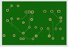
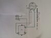
6700i before changes:
LT-6700-I Prototype Schematic.jpeg


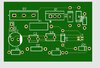
4/23/21 UpDate Schematic 6700i
6700i Schematic update 4-23-21.jpeg


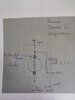
Scope set at 0.1 volts/div and 1 cm below center, final configuration e input ripple about is about 0.04 Volts PP ready for another test on the car:
6700i input ripple final.jpeg


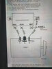
6700i, Scope set at 2 volts/div Field Output signal.
6700i Field Output Scope.jpeg
 
Last edited:
I am new here and I am very interested in your 350 6v voltage reg for my citroen traction avant 11bl from 1953. I ordered the components but I am not sure of the values of the C (condensator)components. You used three of them can you give the value of them? My dynamo is 25A 6 Volts so i use STPS40L15.
 
Wow! "beefto" You're a brave Soul. Be sure to check that your car is Negative ground and that the generator uses a "B Circuit" According to this website **broken link removed** and others the Bosch VW Porsche 6 volt Dynamo I have been working with are in the "A Circuit" category!
Here is the latest Schematic for the 350 and a couple of photos of the latest prototype of it.
0.10 Microfarad Capacitors, Mylar Capacitors, are used for noise suppression, I omitted the 0.10 uF on the input of the last 350 prototype and any (10 or more volt 220 uF or more Microfarad for the "U" power supply filter capacitor will work). The last capacitors I got were 1000 uF Microfarad at 10 volts but the 220 worked well and were smaller.
I used a different MOSFET below which worked well however the IRF-540 or the NTP75N03HD have also been used. But the only other updates are just the STPS80L15 and the 50 ohm resistor to B+ added so I couldn't accidently burn anything up. The STPS40L15 Diodes in the TO-247 Package worked ok on my 55 Amp Dynamo. Note! (It's good to mount the cutout diode to something it can dissipate heat to.) Let me know how it went and post a photo here if you can.
Schematic 350 update.jpeg


Note! Photo below has a 7.5 Volt Zener Diode and a 6.8 which if removed raises the generator output to 7.5 volts, while the Schematic above only shows the 6.8 and a 4.7 Volt Zener in the "U" supply which is needed to meet the low 5.5 volt maximum supply voltage requirements of the ADCMP350 Comparator. A 3.3 Volt regulator or a LM7805 5 volt voltage regulator could replace 50 ohm resistor and 4.7 volt zener diode near top of the schematic above.
The lower value 6.8 Volt zener diode on the green terminal block sets the Dynamo output voltage. A little more or Less voltage may be needed for it on your car.
Finalized Prototype 350.jpeg


Finalized Prototype 350 Bottom_2.jpeg
 
Last edited:
Thanks Danwvw appreciate. Yes I have a B-Circuit. I ordered the parts. I give you a message when I start and end the project.
 
Started a LM-393 comparator current regulation version that uses the ACS773 Hall Effect Sensor to measure the current and to limit the generator output if the Amps exceeds 50 Amps. This circuit is different than the 6700 in that voltage references will be external with the Current Ref voltage being 3 volts and the voltage ref will be 0.6 volts.
April 10th UpDate Fully tested and operational on the car. It was necessary to power the LM-393 from the B+ circuit for it to start charging properly. (Note! This design does not seem to have the over charging problem the 6700 did, and generator output voltage is more stable than all previous designs.)
April 13 Update, Today was eventful regarding the 393i The current regulation is good to within a fraction of 1 amp.
Testing involved leaving the headlights on for 1 hour with the car parked. Then a 15 minute trip to town with headlights on. Turned it off at the bank and noticed the Gen Lite came on. The problem only got worse as we had a few more stops. Eventually discharging the battery to the point of almost. not. starting. Had to idle it to keep it happy. The STPS80L15 was over 100' C The overheating stopped once I got it cooled down. These Oring diodes need a cool heat sink. I may have to move the location to outside the engine compartment. This is the first one to do this, the previous version 6700i did not reverse breakdown like this 395i prototype. I did get it awfully hot. Neary burning me to touch the regulator housing. But other than the unhappy STPS80L15 Cutout diode this regulator was functioning perfectly regulating both current and voltage stabley.
Note! (The STPS80L15 and the STPS40L15 with use exhibit big < changes in VF VR measurement Using diode check).

395i On the Scope bench test:

393i with Hall Effect Schematic Final Version with LM-393 VCC running off of B+ circuit.


395i Prototype started, underside:
Up Dated 393i Prototype (1) With IR Barrier Diode:
Mechanical Regulator Disassembly.jpeg
393HallEffectPrototype.jpeg


Barrier Diode Updated to IR82CNQ030 80 Amp :
Prototype 393i (1) IR Updated.jpeg
Schematic 325i (1)
393i Schematic Final.jpeg


On The Scope!
Scope 393i.jpeg

Capacitors and 3.3 Volt Regulator located on the Under Side of the Board:
393i Prototype Side View.jpeg


April 8 2021 Update 393i Hall Effect Prototype, top side:
393HallEffectPrototypeProgress.jpeg


325i Top view with 1.2 volt reference IC installed.:
393i Prototype Top View.jpeg


395i Prototype Side View showing 1000uf and 100uf and the 3.3 volt regulator below the board:
 
Last edited:
Thanks Danwvw appreciate. Yes I have a B-Circuit. I ordered the parts. I give you a message when I start and end the project.
Double check your circuit turns out these designs are for "A Circuit" Generators. It's where the regulator goes in the generator that makes it an "A Circuit" or "B circuit" Generators with the internal field connected to Positive D+ like these are considered "A Circuit" If yours is a "B circuit" the internal field connection is to ground so not any of the designs above would work. Not sure how to do a "B Circuit" as it would require a P channel Mosfet I think. Totally different. Kind of need to take a generator apart or measure the connections using a headlight and a car battery for a ohm meter as on a regular digital multimeter the field coil and armature are going to measure zero ohms.
 
I am not a electronic designer but I understand the simple easy-eda pcb program.
Here some homework I made and ordered a pcb (10) double layer for the adcmp350 prototype feb 12.
 

Attachments

  • pcb4.JPG
    pcb4.JPG
    42.1 KB · Views: 308
  • pcb3.JPG
    pcb3.JPG
    25.6 KB · Views: 295
beefto You should not have ordered the board so fast. I'll make a few immediate comments.

1. Mounting holes
2. heatsinks.
3. Traces may not be up to handing the current - especially the rotor current
4. One pad on the rear looks suspicious
5. You should have done a "copper pour". This makes the board faster to etch because the unused area is filled with copper with a border around the trace perimeter.
6. High current and reference grounds need to be kept separate and joined at one spot.
7. Dan should have checked over your schematic.

Comments are general and not specific.

I learned how to do it the hard way with tape at 4x magnification at an Explorer's post at HP. Our group of 3 was the second to complete assembly and the first one working. One trace fell off and there were defective parts.

I too have been playing with easyEDA. Not so easy for me. I wanted to make a pad that needed to be 1.5mm fromthe edge and have a via not in the center. I was told to use polygons.

I have to make my own footprints and symbols even though I'm using very few parts. One board will have 3 IC's, a couple of LEDs, a few resistors, test points, and wire tie points. Essentially made similar to these: https://www.capitaladvanced.com/uni-sip.htm.

Today, I spent working on another schematic (reverse engineering) and found out that "grouping" isn't an option.
Hey, I fixed the device. It's been not working for 4 years, It happens to be a spare phone charger base which never worked from day 1. I'd love to figure out how to do simulations.
 
beefto You should not have ordered the board so fast. I'll make a few immediate comments.

1. Mounting holes - Yes Mounting Holes!
2. heatsinks. NA (Not needed at least if the cutout diode does not mount to the board as it does need a heat sink!)
3. Traces may not be up to handing the current - especially the rotor current NA (neither the field or rotor current go through the board.)
4. One pad on the rear looks suspicious
5. You should have done a "copper pour". This makes the board faster to etch because the unused area is filled with copper with a border around the trace perimeter. Great Idea!
6. High current and reference grounds need to be kept separate and joined at one spot. Yes but if the design was followed they were. (I haven't traced it out yet to see though.)
7. Dan should have checked over your schematic. I would be happy to.

Comments are general and not specific.

I learned how to do it the hard way with tape at 4x magnification at an Explorer's post at HP. Our group of 3 was the second to complete assembly and the first one working. One trace fell off and there were defective parts.

I too have been playing with easyEDA. Not so easy for me. I wanted to make a pad that needed to be 1.5mm fromthe edge and have a via not in the center. I was told to use polygons.

I have to make my own footprints and symbols even though I'm using very few parts. One board will have 3 IC's, a couple of LEDs, a few resistors, test points, and wire tie points. Essentially made similar to these: https://www.capitaladvanced.com/uni-sip.htm.

Today, I spent working on another schematic (reverse engineering) and found out that "grouping" isn't an option.
Hey, I fixed the device. It's been not working for 4 years, It happens to be a spare phone charger base which never worked from day 1. I'd love to figure out how to do simulations.
 
Yeah, I didn't put the MOSFET DRAIN and Source on the board. I mounted the MOSFET to the Old Mechanical regulator body. Better to just abandon the idea of mounting it on the board. It can be done with trench Power MOSFET's the Dynamo field current will likely only be 5 or 10 amps so with good traces it can be done with a better choice in a MOSFET. Look for one with great low voltage gate performance. Low Forward Voltage Drop. Low esr down in the single digit milliohms, probably find a surface mount one.
 
Last edited:
The Board Looks right to me, (trace and component wise). Just make the B+ and D+ connections at the cutout diode and MOSFET Drain and Source (ie Main GND) connections to the generator. That should keep the current off the traces. Ps: Also probably omit C3 i did not use it.
pcb4.JPG
 
Last edited:
If this board just had a hole in the middle for the regulator cover screw and a couple of others to mount it, it would make building the VW 6 volt Electronic Regulator quite easy! I don't know what is happening with "beefto"? Probably got discouraged if he discovered the "A Circuit" Regulator is wrong for the 53 Citroen Avant. It could be a real challenge to figure out the "B Circuit" with a P channel MOSFET. It has me wondering! Maybe use the N Channel and figure out how to gate it with 12 to 15 volts so it would operate on the high side. I did it on my 12 volt turn signal flashers with a voltage doubler circuit.
 
Last edited:
For a "B Circuit" Maybe something like this would work: (Voltage Doubler Updated 4/17/21 with optimized capacitor values and 25 ohm resistor, bench testing with the 6700i "A Circuit" old prototype it produced 14.3 volts at 2.3ma with 6.1K load.) The question here is whether or not this design would start charging or just stick 1/2 on?
B Circuit Regulator Schematic UpDate.jpeg
 
Last edited:
Hi Danwvw I am ordering some parts. I am still thinking that your circuit feb 12th 2021 met my alternator 6v dc. Some background the mechanic regulator has 3 functions a voltage regulator , a current regulator and a counter current regulator. Mass is car chassis, 6v DC alternator .
 

Attachments

  • alternator.jpg
    alternator.jpg
    249.2 KB · Views: 299
  • alternator1.jpg
    alternator1.jpg
    7.6 KB · Views: 279
  • alternator2.jpg
    alternator2.jpg
    148.9 KB · Views: 330
  • traction1.jpg
    traction1.jpg
    201.4 KB · Views: 301
Not sure what a counter-current regulator is?
Nice looking car?

Positive or negative ground?

Dan is trying to do the voltage regulator and current limiting.
 
Dan is also doing this for a generator, isn't he? Alternators and generators have different regulators, to my knowledge they aren't inter changeable.
 
in principle, the regulator design isn't that different.

Generators can be used as motors, alternators can't.
Different terminology. Alternator: rotor and stator; Generator has the field and permanent magnets
Alternator is lighter.

In general:
Biggest difference is whether you control with a positive or ground switch.
Positive or negative ground.
6 vs 12V
 
Status
Not open for further replies.

Latest threads

New Articles From Microcontroller Tips

Back
Top