Continue to Site

Welcome to our site!

Electro Tech is an online community (with over 170,000 members) who enjoy talking about and building electronic circuits, projects and gadgets. To participate you need to register. Registration is free. Click here to register now.

  • Welcome to our site! Electro Tech is an online community (with over 170,000 members) who enjoy talking about and building electronic circuits, projects and gadgets. To participate you need to register. Registration is free. Click here to register now.

audioguru`s FM transmitter

Status
Not open for further replies.

chomyunghyun

New Member
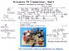
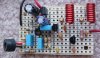
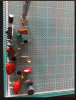
I have made aduioguru`s FM transmitter mod3. It`s working but my transmitter has much noise.
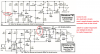
so I made mod4. but it dosen`t work absolutely.
I changed audioguru`s circuit
1) LM2931A => LM7805
2) 35p trimmer -> 30p trimmer.
3) 3mm former 8 turns -> 3.5mm former 8 turns
I think what my problem is trimmer. Carrier frequncy can`t reach to 88~108MHZ. How do you think? Do I have to change coil 7 turns?

sorry sir.. i have a few question.
1. what is purpose of mod3`s c9 100uF capacitor? for removing DC?
2. what is purpose of mod3`s c5 4.7pF capacitor? bypass for signal?
2. what is purpose of mod3`s c7 capacitor? i don`t know why you design c6,c7 cascade capacitor.
 

Attachments

  • FM transmitter.PNG
    FM transmitter.PNG
    342.4 KB · Views: 267
Last edited:
The 100uF removes the ripple and hum from the DC supply and 4.7pf feedback cap keeps the oscillator oscillating. Maybe he was trying get correct combination of pre-emphasis with R5, R8, C6 and C7. Mod 4 has easy setup of the pre-emphasis.

If your new Mod 4 has correct wiring then you can stretch or compress the coil to adjust frequency. But if you have trimmer capacitor then the trimmer will do the job. Turn in the radio receiver and tune blank frequency, then turn on and off the transmitter. If you heared any interference or difference then the transmitter has frequency problem, otherwise you have to check the assembly/wiring again.
As my experience, you have made little high inductance coil. 24 SWG 6 turns stretched little coil working on moderate frequency with 10pf fix capacitor (instead of trimmer) on my Mod 4. It has pretty nice audio. Your coil has thicker wire, more turns and compressed coil.
Look at the image of Mod4, I have made. Middle one is L1 which is critically related to frequency.
Ref:
Mod3
 

Attachments

  • FM Mod4.jpg
    FM Mod4.jpg
    57.2 KB · Views: 302
Last edited:
The circuit will not work if made on a solderless breadboard with many rows of contacts having stray capacitance between them and the inductance of all the long jumper wires. It also will not work if the parts are too far apart like a photo I show.
Willen's and mine work well because the circuits are made compact with the parts close together.

The 9V battery quickly drops below 7V as it gets used but a 7805 does not work properly when its input is less than 7V so I used a "low dropout 5V regulator" that are made by most IC manufacturers that works when the input drops to 5.4V.
The low dropout regulator MUST have a high value output capacitor (100uF C11 on mod4) to prevent it from oscillating.

C7 in Mod3 prevents the low value of R8 from upsetting the DC biasing of Q1. R8 and C6 produce pre-emphasis. The extra capacitor is not used in Mod4 because I changed the values for the pre-emphasis.
 

Attachments

  • FM circuit bad.jpg
    FM circuit bad.jpg
    74.6 KB · Views: 225
  • capacitors in FM transmitter.png
    capacitors in FM transmitter.png
    158.8 KB · Views: 267
I forgot to post the photo of my FM transmitter. It is built on stripboard and the strips are cut to length with a drill bit so that each strip is used for a few parts of the circuit.
 

Attachments

  • FM tx mod4 pic.jpg
    FM tx mod4 pic.jpg
    44.7 KB · Views: 236
Status
Not open for further replies.

Latest threads

New Articles From Microcontroller Tips

Back
Top