Electro Tech is an online community (with over 170,000 members) who enjoy talking about and building electronic circuits, projects and gadgets. To participate you need to register. Registration is free. Click here to register now.
Welcome to our site! Electro Tech is an online community (with over 170,000 members) who enjoy talking about and building electronic circuits, projects and gadgets. To participate you need to register. Registration is free. Click here to register now.
A transistor that clamps the input signal causes severe distortion. A Jfet is usually used as a fade circuit instead.
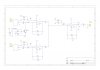
Your transistor is changing the DC voltage of the inverting input of the opamp which causes its output voltage to jump near the positive supply voltage when the transistor turns on causing the POP.
R16, R18 and R20 in your circuit do nothing and can be replaced by a piece of wire.
There are THREE bias networks (R4 and R5, R7 and R10, R12 and R13) when only ONE network is needed that can bias hundreds of opamps. Usually the junction of the bias resistors has a capacitor to ground to attenuate power supply noise.
This site uses cookies to help personalise content, tailor your experience and to keep you logged in if you register.
By continuing to use this site, you are consenting to our use of cookies.