Continue to Site

Welcome to our site!

Electro Tech is an online community (with over 170,000 members) who enjoy talking about and building electronic circuits, projects and gadgets. To participate you need to register. Registration is free. Click here to register now.

  • Welcome to our site! Electro Tech is an online community (with over 170,000 members) who enjoy talking about and building electronic circuits, projects and gadgets. To participate you need to register. Registration is free. Click here to register now.

Astable Multivibrator

Status
Not open for further replies.

mitch

New Member
G'day all,

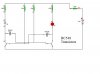
Am new to electronics and chasing some help. Have to make a astable multivibrator. We are powering it with one 9v battery, running through a protection diode. This then goes to four resistors, two 10k and two 390. The line following the 390's then goes into the LED's and after which is then cross coupled thorugh capacitors and into the transistors. What i am after is that i need to find a source (website) that tells me why these size resistors are used, and same for the capacitors and also the transistors.

I am using 100uF 16v capacitors, then removing these and fitting bigger ones up to 470uF and 16v. I know that as they get bigger the flash rate slows down, but need to find a reliable source that syas why to include with the circuit

thanks,
mitch
 
The capacitors and the 10k resistors form the timing parts, while the 390 ohm resistors provide pullup current. The 390 resistors must be much smaller than the 10k or the cct may fail to operate. The 390 resistors also limit the current flowing through your LEDs.

A cct explanation:
**broken link removed**
 
Here is a pic of it drawn in a program, dont have pic of actual set-up on me at the moment.
 

Attachments

  • croc.jpg
    croc.jpg
    17.8 KB · Views: 402
Your drawing looks wrong, but dougy has a good explanation for the 'correct' circuit.
 
There are a couple of things wrong with your circuit-the timing capacitors are reversed(they should be connected with the +side connected to the timing cap and resistor then the base of the switching transistor),and the 390R resistor isnt needed-increase the led series resistors to 470R-plus by adding a few extra parts as shown in my schematic the leds flash is a bit better .... instead of increasing the value of yr timing capacitors try increasing the value of the timing resistors which will also slow the circuit down.....do not be scared of it!!!!
 

Attachments

  • astable multi.pdf
    8.5 KB · Views: 345
Last edited:
His drawing looks fine to me. The capacitors are correctly orientated - the transistor base never goes above 0.7V, while the collector can approach the rail voltage. Maybe the 390R is not a usual addition, but I can't see it not working.
 
I don't think the 390 belongs in there. And, following his desctription, the collector resistors are supposed to be 390. Looks like he just got confused. If he made the collecotr resistors 390 and removed the extanious one, it would be fine.
 
Why did Sheldon post a circuit that does not work and it has two extra transistors?
 
Looks ok to me. You dont need the 390 by the battery. The waveforms look better without it.

btw, this should answer the question about using polarized capacitors.
 

Attachments

  • AstableLEDs.jpg
    AstableLEDs.jpg
    188.5 KB · Views: 527
Last edited:
Has there ever been a practical use for the multi-vibartor? It was probably the first circuit I every built, and I've experimented with dozens over the years. But has any serious use of them ever been made?
 
Has there ever been a practical use for the multi-vibartor? It was probably the first circuit I every built, and I've experimented with dozens over the years. But has any serious use of them ever been made?

They are used in many circuits, anywhere you want a squarewave oscillator.

The Stylophone used two of them I believe?.
 
for one the circuit ive posted does work and it works very well the two extra transistors added ensure the leds when they switch on and off do so quite rapidly if u connect them as his first drawing shows the leds seem not to switch as cleanly as they do when you add an extra transistor....the electrolytics in my schematic are the wrong way round...plus it seems i missed a couple of resistors out ..i think i need glasses!!!...if you are in any doubt as to wether the circuit iv posted will work ill build you one and post it to you.......as per my schematic.......dont be scared of it!!!
 

Attachments

  • astable multi.pdf
    8.4 KB · Views: 415
Last edited:
I say "build it" and post it. I don't think it will work either. Transistors Q1 and Q2 will keep the others cut off. I just think there's a mistake in the drawing.
 
glasses are now on order-corrected version is here that does work as per the schematic ive uploaded-do not whatever you do be scared of it!!!...........
 

Attachments

  • astable multi.pdf
    8.5 KB · Views: 246
Last edited:
Sheldon,
Your circuit is wrong. I corrected it but it does not need 4 transistors and will work fine with only 2 transistors.
 

Attachments

  • sheldon's multivibrator.PNG
    sheldon's multivibrator.PNG
    33.4 KB · Views: 233
if you look ive already corrected my uploaded drawing....dont be scared!!!...........
 

Attachments

  • astable multi.pdf
    8.5 KB · Views: 204
Please explain in words how this is supposed to work????

I'm not familiar with that particular transistor, but it they have a forward gain of more than 2, then q1 and q1 will be saturated, even so for guru's circuit, if the gain is more than 10.
 
Status
Not open for further replies.

Latest threads

New Articles From Microcontroller Tips

Back
Top