Continue to Site

Welcome to our site!

Electro Tech is an online community (with over 170,000 members) who enjoy talking about and building electronic circuits, projects and gadgets. To participate you need to register. Registration is free. Click here to register now.

  • Welcome to our site! Electro Tech is an online community (with over 170,000 members) who enjoy talking about and building electronic circuits, projects and gadgets. To participate you need to register. Registration is free. Click here to register now.

astable multivibrator

Status
Not open for further replies.

PG1995

Active Member
Hi,

Could you please help me with the questions below about astable multivibrator?

Question 1:
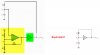
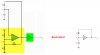
Please have a look here. Is the input voltage, Vin, going to be lower than the output voltage, Vout?

As soon as Vin is applied, Vout goes HIGH and as it's greater than Vin therefore current starts flowing from the output, Vout, into capacitor C through R.

Question 2:
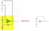
This question is also based on the text from Question 1. Are the shown circuits equivalent? In yellow we have schmitt trigger, green is inverter.

Thank you!
 

Attachments

  • Symmetrical-Schmitt-Trigger.jpg
    Symmetrical-Schmitt-Trigger.jpg
    43 KB · Views: 306
  • astable_vibrator.jpg
    astable_vibrator.jpg
    239.5 KB · Views: 311
Vout will switch to (almost) supply voltage and 0V, depending on input level.

Once the oscillator has stabilised, the input voltage will probably range between about 1/3 and 2/3 supply. Each time the cap charges or discharges to the input switching threshold, the output will change state and swap between charge and discharge.

The other circuits are not equivalent as the first stage is an inverter, then with a second inverter added. There is no overall inversion so it will stay in one state or the other rather than oscillating.
The feedback resistor would have to be moved to the output of the first stage to make that an equivalent; the added inverter is then redundant.
 
Thank you!

Vout will switch to (almost) supply voltage and 0V, depending on input level.

But the input voltage, Vin, doesn't need to be equal to the supply voltage.

The text says, "When power is first applied, the capacitor has no charge; so the input to the Schmitt trigger inverter is LOW and the output is HIGH. The capacitor charges through R until the inverter input voltage reaches the upper trigger point (UTP), as shown in Figure 7–55(b)".

Perhaps, Vin, is not really an input voltage; I mean perhaps it's not an externally applied voltage. The label 'Vin' has just been used to refer to that node.

The other circuits are not equivalent as the first stage is an inverter, then with a second inverter added. There is no overall inversion so it will stay in one state or the other rather than oscillating.

Isn't the first stage, highlighted in yellow, just a schmitt trigger circuit?

By the way, this is actual schmii trigger I used. Perhaps, a schmitt trigger circuit in itself an inverter circuit?

The feedback resistor would have to be moved to the output of the first stage to make that an equivalent; the added inverter is then redundant.

Like this?

Thank you for your help and time!
 

Attachments

  • Symmetrical-Schmitt-Trigger_new.jpg
    Symmetrical-Schmitt-Trigger_new.jpg
    42.8 KB · Views: 285
  • schmitt_trigger_111.jpg
    schmitt_trigger_111.jpg
    60.9 KB · Views: 299
Perhaps, Vin, is not really an input voltage; I mean perhaps it's not an externally applied voltage.
Exactly; it's internal to the oscillator section.

Isn't the first stage, highlighted in yellow, just a schmitt trigger circuit?
Yes, but the way it is configured means the output is inverted relative to the input, the same as with the single CMOS inverter version.

Near enough, except for the extra inverter on the left hand version.
 
Thank you, rjenkinsgb .

Please have a look here. I have removed the inverter. Is it more like it now?

Assuming I have it correct now, Is the configuration called 'inverter with hysteresis'? As a matter of fact, all my confusion started with second para from original text where it is said, "Figure 7–55(a) shows a simple form of astable multivibrator using an inverter with hysteresis (Schmitt trigger) and an RC circuit connected in a feedback arrangement". I started asking myself 'how does an inverter with hysteresis look like?'.
 

Attachments

  • Symmetrical-Schmitt-Trigger_new2.jpg
    Symmetrical-Schmitt-Trigger_new2.jpg
    37.9 KB · Views: 307
Last edited:
Assuming I have it correct now, Is the configuration called 'inverter with hysteresis'?
Yes.

The hysteresis part makes it a schmitt trigger, whether it inverts or not.
The inversion allows it to work as an oscillator in that configuration.

A 555 timer can be thought of in a similar way; the hysteresis is produced by two separate voltage comparators rather than changing thresholds via feedback as with your example circuit, but the end effect is similar - two different voltage thresholds which cause the output to change state.

See the diagram "50% Duty Cycle Astable Oscillator" half way down this page, for a 555 osc circuit that's pretty much equivalent to the schmitt trigger inverter oscs.
**broken link removed**
 
Status
Not open for further replies.

New Articles From Microcontroller Tips

Back
Top