Electro Tech is an online community (with over 170,000 members) who enjoy talking about and building electronic circuits, projects and gadgets. To participate you need to register. Registration is free. Click here to register now.
Welcome to our site! Electro Tech is an online community (with over 170,000 members) who enjoy talking about and building electronic circuits, projects and gadgets. To participate you need to register. Registration is free. Click here to register now.
Sine wave oscillators are very complez designs that would require different driving stages. I would use an MCU, or ic555 and cd4047, but I just wanna be a little bit non-complex for a while
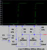
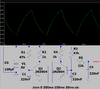
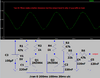
Here is a simulation of the squarewave, then with one RC filter to make a lower level triangle waveform, then with two RC filters to make an even lower level poor sinewave:
Ok. I see now. I am thinking of an RCL circuit, mabe that would do the trick and also, how do I calculate the values of R2 and R3 in an astable multivibrator? Its really confusing to rearrange the formula..
Since you apparently only need a single output it would be better to use 555 timer, the formula is well established with very predictable and stable frequency obtained.
Best to use trigger and threshold together with capacitor to ground and feed output via resistor to capacitor. This way you get 50/50 duty ratio and good output capability. Basically the 555 is acting as a Schmitt trigger inverter with large hysteresis of 1/3 Vcc.
I also like IR2153 and have 2 outputs for driving MOSFET or IGBT. Great for transformer driving as per you original circuit and there is dead time between outputs of 1.2uS not quite 50% duty, but not an issue @50Hz. It is really a half bridge driver with Hi out up to 600v.
I have a PIC16F72 inverter, I'm trying to see if I could Replicate the sine'ish' wave, is more like an Experiment. No big deal. A square wave generator needs some caps and resistors to get a sine wave. But a sine wave inverter would need cross-coupled ICS, related to get a sine wave. Its kind of like a self project.
I have a concern about what I think you are doing. If your intention is to generate 50Hz from 2 outputs then filter them to approximate sine waves, then drive a mains to CentreTap low voltage transformer from the secondary to get mains voltage from 12v or something like that, I.e. make an inverter. You are probably going to blow up a lot of components and not achieve the result you are seeking. Your biggest problem is the low inductance of the transformer's low voltage winding. At 50Hz there will be a lot of current that will mostly heat the transformer and your power transistors. This is why these things are done at high frequencies using PWM. And the filtering is on the output using smaller components. If it was easy, don't you think the commercial products would be simple?
In post#1 he asked about the multivibrator oscillator, not the entire inverter circuit.
in post #4 he said, " I just need only the oscilllator."
In post #12 he said, "My Proposed circuit is an astable multivibrator".
In post #17 he said, " I just needed an astable multivibrator".
A sinewave inverter does not make a sinewave then amplify it to make a mains voltage. That would waste about half the battery power making the output transistors VERY hot.
Instead, a sinewave inverter uses high frequency Pulse-Width-Modulation circuit to make a sinewave with many "voltage steps" then filters it to smooth the steps into a sinewave. The output transistors switch completely on (no voltage) then switch completely off (no current) to avoid heating.
Since the switching frequency is ultrasonic then a small inexpensive ferrite-core transformer is used.
Here is a sample of a Pulse-Width-Modulation waveform before smoothing:
Yeah I know what he said, I'm just reading between the lines and recalling the original diagram which showed a very basic inverter. I was just giving a warning that at low frequencies you would probably get lots of dead components if that's what you did. And you confirmed what I said about PWM and small components to filter, albeit with a little more detail.
The very old circuit you posted produces a squarewave 50Hz output from its transformer. The squarewave was fine for old incandescent light bulbs and old heaters. A transformer that works at 50Hz is huge and heavy.
Modern inverters use Pulse Width Modulation to make a pure sinewave and the pulses operate at 25kHz or higher so that the transformer can be small and have a ferrite core. Many modern products do not work properly from a squarewave and require the electricity to have a sinewave.
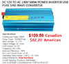
Here is a typical modern 500W pure sinewave inverter:
No they don't, as far as I'm aware ALL invertors use small switch-mode transformers, and have done for many, many years - antique inverters used large transformers, and were expensive and inefficient for that reason.
I dont think "Miracletech" is really learning much here. He/She(?) Keeps making statements based on assumptions. I think it's time to leave them to it.
This site uses cookies to help personalise content, tailor your experience and to keep you logged in if you register.
By continuing to use this site, you are consenting to our use of cookies.
")