Continue to Site

Welcome to our site!

Electro Tech is an online community (with over 170,000 members) who enjoy talking about and building electronic circuits, projects and gadgets. To participate you need to register. Registration is free. Click here to register now.

  • Welcome to our site! Electro Tech is an online community (with over 170,000 members) who enjoy talking about and building electronic circuits, projects and gadgets. To participate you need to register. Registration is free. Click here to register now.

ARES1 Work in progress

Status
Not open for further replies.

Krumlink

New Member
As you may or may not know, a lot of my robotic projects (ViPER, TrackBot) never took off, mainly because I did not have the tools or the expertise. Well after studying the 18F2525 Datasheet for many hours straight, I am ready to release the specifications of my robotic pinnacle:

ARES1
Advanced Robotic Experimentation System 1

Ares will be built into modules, like the ViPER system, but it will include the robotic delivery system of the trackbot. Each module (or a couple modules) will be mounted on a 5" by 2 1/2" of lexan, 1/8 of an inch thick. The Treads will also be mounted on one of the layers. The ARES1 Motherboard will consist of a 40pin, 28pin, and 18pin version. So far the 28 pin is closest to completition. It will be using a 18F2525 and will have all ports avaliable (except for MCLR of course). The reset switch is a copy of the Junebug reset switch, except for the added LED and a 1K resistor added in parallel to lower the resistance of the 22K resistor. It connects and programs just fine with the Junebug and Inchworm+ (now collecting dust, first time I pulled it off the shelf :))

So far I am quite happy with how the design is going. ARES1 will be the centerpeice of my empty website. I also already have a program for ARES1 which will be released when the robot is complete. Modules that will be built are:

LCD Module (Complete and working)
PWM and Sensor interface Module
Motor Controller Module
Automatic Battery Charging Module (Currently being tested)
I2C Module (needs to be researched)
Parallel PIC communication Module
Encoder Interface Module
*If you have an idea for a module send me a Private message to keep this thread clean*
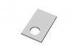
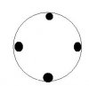
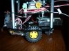
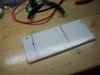
ARES 001
A picture of one of the lexan pieces. I am making better ones today.
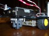
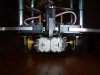
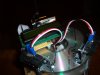
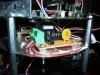
ARES 002
Picture of the Motor, bracket and a SHARP IR sensor
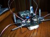
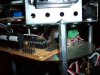
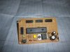
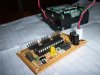
ARES 003
Picture of the ARES1 Motherboard, with a 18F2525 in. The LED's appear lit but they aren't. The green LED is the reset LED which turns on when MCLR is low.
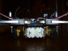
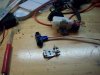
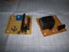
ARES 004
Pictures of the LCD Module on the left without LCD and the Automatic Battery Charger. It will signal a LED and a alarm when the voltage drops too low. It could also trigger the robot to look for a power source, an idea that I have.
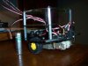
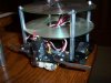
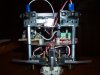
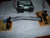
ARES 005
Picture of the 8 AA rechargeable batteries and the ARES1 Motherboard. The power connector will come from the Automatic battery charger board, but in this situation it is powering the 5VDC regulator directly, another feature to move around.
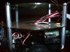
ARES 006
LCD Module plugged in for effect. It is not programmed nor is the 2x5 header on the ARES1 motherboard connected up.

Commenting Open
 

Attachments

  • ARES 002.jpg
    ARES 002.jpg
    326.7 KB · Views: 246
  • ARES 003.jpg
    ARES 003.jpg
    432.5 KB · Views: 264
  • ARES 001.jpg
    ARES 001.jpg
    256.5 KB · Views: 242
  • ARES 004.jpg
    ARES 004.jpg
    408 KB · Views: 235
  • ARES 005.jpg
    ARES 005.jpg
    455.5 KB · Views: 258
  • ARES 006.jpg
    ARES 006.jpg
    457.1 KB · Views: 236
Last edited:
I have decided to not use the treads because of problems I encountered while mounting them. I will instead be using Wheels. Pictures and more to come soon.
 
After even more complications with the body I have decided to use the Pololu laser cut body with the Tamyia gearbox. Everything is now working the way I want it to :)
 
Here is what I wrote for ARES1 on letsmakerobots.com

ARES1 Will pick up where ViPER left off. ViPER was not going to work because of poor planout of the modules and the fact that I did not have a robot body planned for it. ARES1 Is where ViPER failed because of these problems. The first thing I did was make sure that ARES1 uses the same 2x5 header, primarily because it accomodates for all 8 I/O ports and 2 for the power and GND pins. All modules are done on Veroboard, perfboard, etc whatever your local dialect calls them.

The ARES1 System will use the Pololu Round robot chassis (which is excellent), a Tamyia 70097 Gearbox (also perfect, a slight bit squeaky though) and a Metal ball caster, which is the best caster I have seen. The gearbox will run on 4.8VDC, While the electronics will be run on a 5VDC regulated supply. There are possible plans to power it with a Buck/Boost Charge pump. The Motors will have a isolated (the 4.8VDC power pack) supply to eliminate all electrical noise in the nearby circuits. The motors also have spike capacitors to remove high voltage spikes. The motors will be driven with a SN754410 Motor controller, which is perfect in this situation. The Motor supply will also have a voltage charging/monitoring system, where if the voltage drops below 4.45VDC it will signal an LED to indicate it is time to charge the motor batteries. it may be controlled with a dedicated microcontroller just to add to the sophistication. The MCU will be running the ADC's to determine the exact voltage level, which is better than a comparator where it can lose accuracy as its own power supply drops.

Explanation of the pictures:
ARES 001
This is a picture of the main controller board, a 18F2525 (picaxe pfft!) with reset button and reset indicator. The LED indicates when the chip is held in reset. For testing I added a 5VDC regulator and a bulk capacitor. Those will be removed once the power board is complete. In the top of the controller board there are 4 2x5 headers. going from left to right they are: Program port, PORTA PORTB PORTC. The Yellow LED indicates power.

ARES 002
Picture of the ARES1 controller being powered by a 9.6VDC power pack. That will no longer be needed, as there will be a dedicated power board.
ARES 003
Picture of the robot with motor wires hanging out. Those will be shortened and fixed up. Whisker switches/micro switches are also visible with their wires (chopped off PWM servo wires) hanging out. Those will be attached to 3 pin female connectors;
ARES 004
Front of the robot. You can see the motors and the capacitors attached to them. Another shot of the switches.
ARES 005
Rear of the robot with metal ball caster in position. You can also see the battery pack. it is there to weight the back of it down and to add stability. Overall this robot will be very solid and tough once completed. You may also see the zinc spacers which will accomodate the upper decks. I highly suggest any noob to start out with this, as it is simple to assemble and operate. I myself was unable to properly construct a robot base so instead I went with a precise robot body.
 

Attachments

  • ARES 001.jpg
    ARES 001.jpg
    432.5 KB · Views: 238
  • ARES 002.jpg
    ARES 002.jpg
    455.5 KB · Views: 221
  • ARES 003.jpg
    ARES 003.jpg
    417.1 KB · Views: 240
  • martian-logo.jpg
    martian-logo.jpg
    23.9 KB · Views: 218
  • ARES 005.jpg
    ARES 005.jpg
    414.3 KB · Views: 238
  • ARES 004.jpg
    ARES 004.jpg
    417.8 KB · Views: 240
Commenting open

ARES1 is really starting to come together.

ARES 006
Side view of bumper switches (left, front and right) as well as the battery pack in the back. You can also see all the wires coming out of the side as well, which will be wired up soon.
ARES 007
Front of the robot with the sensors. This will allow ARES to know if it hits any walls and will react accordingly. All programming will be done resembling NAOS multitasking.
ARES 008
Another side view of ARES1. If you see, you will notice and realize that the CD's are smaller than the base, preventing me from drilling through the CD. I had to "Pinch" the CD's with the standoffs to ensure that ARES will not fall apart while driving around, dragging its guts everywhere (ew!).
ARES 009
Sideview of the 2nd platform. You can see all the wires coming out of the very small CD holes. With this many wires through it so far it gets quite difficult to fit headers and etc through it.
 

Attachments

  • ARES 006.jpg
    ARES 006.jpg
    416.6 KB · Views: 234
  • ARES 007.jpg
    ARES 007.jpg
    408.9 KB · Views: 224
  • ARES 008.jpg
    ARES 008.jpg
    414.6 KB · Views: 262
  • ARES 009.jpg
    ARES 009.jpg
    427 KB · Views: 236
Last edited:
Looks cool, only one comment. Is there any reason you did not just drill holes in your CD platform? The current setup looks like weak supports on the CD's. At very minimum I would add washers or little metal tabs sandwiched over the CD's. Metal tabs as shown in image.

At any rate looks cool so far. Good job...
 

Attachments

  • tabs.jpg
    tabs.jpg
    7.3 KB · Views: 229
I may have mis-worded it. There are little nubs drilled out of it. Bah just look at the picture. The black is the part that the standoffs go through, and it turns out quite nicely.
 

Attachments

  • imsorryforthisjunkimage.JPG
    imsorryforthisjunkimage.JPG
    5.2 KB · Views: 215
Oh, I could not tell from photo. In that case, never mind :)
 
You can see all the wires coming out of the very small CD holes. With this many wires through it so far it gets quite difficult to fit headers and etc through it.

You might want to consider using common ground and power wires. Thus you will have signal wires (n) plus two through the CD holes. That is common practice in airplanes (both full size and models) and many other applications where space is limited.

John
 
You might want to consider using common ground and power wires. Thus you will have signal wires (n) plus two through the CD holes. That is common practice in airplanes (both full size and models) and many other applications where space is limited.

John

Thats a really good Idea, I will try to integrate that.
 
ARES1 was renamed AREVx1 due to a name issue that I found. ARES1 is the name of NASA's newest lunar vehicle.
AREVx1 will have a LCD module, Sensor interface module (for interfacing the Microswitches, IR rangers (18F2525 has ADacs on every port) gyro (once purchased) and accelerometer (maybe, and I need to buy it)) and a Motor controller module. So far The LCD module and Motor module are complete, all that it needs now is the sensor board and main controller to be finished wiring up. I also need to build a power module to supply the entire robot (except the motors and its respective side of the motor controller) with a stable 5VDC supply. I am going to use a LM7805 until I can purchase a LM2940
AREVx1 001
This is the front picture of the robot with bumper switches and IR sensors. You can also see the innards of the robot.
AREVx1 002
Aerial view where you can see the LCD (which will be run in 4 bit mode) and the IR sensors. You can also see the 9VDC battery.
AREVx1 003
Side view of the 2nd deck. You can see 18F2525 and port A with no 2x5 on it. You can also see the motor controller in the background, with the controller board in the forefront.
AREVx1 004
Motor controller board with the green screw connectors and the vital PTC fuse. That will save your robot in a short circuit!
AREVx1 005
Side view of entire robot.

Hope you enjoy the pictures and my hard work.
 

Attachments

  • AREVx1 001.jpg
    AREVx1 001.jpg
    425.1 KB · Views: 245
  • AREVx1 002.jpg
    AREVx1 002.jpg
    419.1 KB · Views: 237
  • AREVx1 003.jpg
    AREVx1 003.jpg
    439.5 KB · Views: 232
  • AREVx1 004.jpg
    AREVx1 004.jpg
    451 KB · Views: 252
  • AREVx1 005.jpg
    AREVx1 005.jpg
    448.2 KB · Views: 239
Status
Not open for further replies.

New Articles From Microcontroller Tips

Back
Top