Continue to Site

Welcome to our site!

Electro Tech is an online community (with over 170,000 members) who enjoy talking about and building electronic circuits, projects and gadgets. To participate you need to register. Registration is free. Click here to register now.

  • Welcome to our site! Electro Tech is an online community (with over 170,000 members) who enjoy talking about and building electronic circuits, projects and gadgets. To participate you need to register. Registration is free. Click here to register now.

antennas and standing waves

Status
Not open for further replies.

whiz115

Member
I'd like to have a better understanding on some RF stuff...

i know a miscalculated antenna has standing waves which is lost energy because the antenna radiates badly... standing waves can harm the output
stage of an amplifier.

i need to know if standing waves are related with impedance mismuch between the antenna and the amplifier so depending the output power there is a posibility the amplifier to get damaged from excesive current draw.

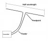
i also need to know why the antenna must be the size of the wavelength or subdivisions of it? i don't exactly understand why the wave must travel its length or subdivision of it's length on the wire before it gets radiated..

thanks!
 
Transmission lines and antennas are governed by a partial differential equation called the wave equation that depends on the three spatial variables and time. The PDE and the boundry conditions allow for only certain kinds of solutions. A standing wave is the part of the solution that depends only on position and not on time. A traveling wave is the part of the solution that depends only on time and not on position. The combined solution is the product of the two solutions. Since each solution happens to be an exponential, the product of exponentials is an exponetial with an exponent that is the sum of the exponents of the individual solutions. This happens when separation of variables is used.

When waves encounter an impedance discontinuity at least two things happen. Part of the energy in the wave is reflected back toward the source and part of the energy continues on it's way.

The geometry of quarter wave and half wave antennas falls out of the boundry conditions to the PDE.
 
Standing waves are indeed a direct result of a mismatch between an antenna and the amplifier. The standing wave is the pattern you get (in voltage or current) when the power travelling to the antenna is superimposed on the power reflected back from the antenna due to mismatch of antenna and transmission line. Power is travelling in both directions at once and when you sum the instantaneous voltage at all points along the line you get a steady pattern of highs and lows. This is the "standing wave".

There are three parts to the problem...the amplifier, the transmission line and the antenna. If the antenna is not matched to the transmission line's impedance then it will reflect some power back to the source. If the amplifier is matched to the transmission line inpedance, then all of this reflected power gets absorbed by the amplifier, which means it has to deal with heat. At the same time, since the amplifier is seeing a mismatch, then yes its current may be higher than it is supposed to be, and efficiency will be lower than it is supposed to be and it heats up, possibly to destructive levels.

Your question of why the antenna must be large relative to the wavelength is a big one and there are whole books written to explain it. However, perhaps a short answer might help. In fact, an antenna does not have to be a significant multiple of a wavelength to function. Many practical antennas are much smaller than one quarter wavelength For example, the short loop is a very common but very small antenna that is used in many places. For example, many garage door opener remotes use such antennas.

Anything can be used as an antenna, its a matter of how well you want it to work. Fifty years ago it was pretty much the rule that any antenna you would run across was indeed large, like quarter or half wavelength. But with the march of technology and the development of so many portable and mobile devices, antenna designers have found that it is often better to simply settle for less performance for the sake of small size.

Theory says that you can make an antenna infinitely small and still achieve good radiation performance if you can do two things. One is that you have to find a way to have lots of current flow in your antenna and the other is that your antenna cannot have any resistive losses at all. Unfortunately, both of these "gotchas" are major roadblocks. It is quite difficult to get a lot of RF current to flow in a very short wire (unless it is a loop) and it is almost impossible to remove all the resistive losses in an antenna. So, in practice, very small antennas are difficult to impedance match to an amplifier, and even then, they are very inefficient radiators (and also have very narrow bandwidth which is an additional difficulty). Most industries that can afford the room have learned to use larger antennas to avoid these problems.
 
really helpful responses.. but...

When waves encounter an impedance discontinuity at least two things happen. Part of the energy in the wave is reflected back toward the source and part of the energy continues on it's way.

reflected energy must be standing waves right?
the main reason for standing waves is impedance mismatch?


Standing waves are indeed a direct result of a mismatch between an antenna and the amplifier.

i need to know if you too mean impedance mismatch or any other kind of mismatch.
 
The main reason that reflections happen is impedance discontinuity. We know that in a properly terminated transmission line there are no reflections, because there are no impedance discontinuities. Any degree of mismatch allows a standing wave to exist.
 
ok...

how antenna impedance gets created? i guess impedance is a result of inductance and inductance a result of antenna mechanical characteristics..

if that's true how come there are antennas for different transmission frequencies 2.4GHz and 5GHz with the same impedance? for a example
if i would like to make a simple telescopic antenna for 2.4GHz i would make one having the size of the wavelegth i need to emit... how do i know if i have 50Ω impedance or whatever?

also i haven't understood the role of the antenna length relative to the wavelength.
 
Lets try a few simple explanations.

The antenna provides a means of coupling electro-magnetic waves (energy) into and out from free space.
Mathematicians and physicists tell us that the impedance of free space is 377 ohms.
As well as coupling the energy, the antenna effectively makes an impedance transformation between its feedpoint and free space.

A halfwave centre fed dipole will have a feedpoint impedance of 75 ohms irrespective of its design frequency.

A folded dipole will have a feedpoint impedance of 300 ohms irrespective of its design frequency.

A quarterwave monopole above a large groundplane will have a feedpoint impedance of 35 ohms irrespective of its design frequency.

The feedpoint impedance is a property of the physical arrangement of the antenna.

Almost all antennas have standing waves on the radiating elements, (there are a few odd exceptions such as the rhombic). The problem with standing waves comes when they are in the feeder from the transmitter to the antenna, they are caused by an impedance mismatch between the antenna and the feeder. If a 75ohm dipole is connected to a 50ohm feeder, there will be a mismatch which causes standing waves in the feeder. This in itself is not the end of the world, but if the feeder were connected to a transmitter which required a accurate 50 ohm load for correct operation, there would be problems.

If we connect our 75ohm dipole to a 50ohm feeder, there will be a VSWR (Voltage Standing Wave Ratio) of 1.5 to 1 in the feeder.
What this means is, if we measure the voltage at various points along the feeder, we will find alternate maxima and minima at quarter wavelength intervals along the feeder, the ratio of the maximum to minimum voltage will be 1.5 to 1.

Enough for now, bedtime I think.

JimB
 
A forum post can only go so far. You really need to find a good reference and acquire enough background so that the explanations we've given start to make sense. Without sufficient background we can talk until we are blue in the face and you won't have any better idea of what is going on. What did you expect exactly? That the concepts were easily explained and understood; I guess I have to apologize for the level of disappointment you must be experiencing. I've given you the best advice I have; I can't do any more.
 
If you want to learn a bit further, here is a very good explanation of why an antenna actually radiates:

ARRLWeb: Why an Antenna Radiates


i have a small one transistor FM transmitter and today i decided to experiment a bit...

i was using the transmitter without any microphone connected... and i was trying to find the carrier frequency on the radio which was difficult because the transmitter is unstable and the frequency was rolling...but i got surprized when i noticed that if i hit a component with the back of the screwdriver then i can hear the noise from the radio like if i was recording the sound.

my opinion is that the vibration was transformed into electrical signals which then transmitted to the radio...and probably the variable capacitor was responsible for that effect... the sound has nothing
to do with bad conduction..

what do you think?!
 
Last edited:
If we connect our 75ohm dipole to a 50ohm feeder, there will be a VSWR (Voltage Standing Wave Ratio) of 1.5 to 1 in the feeder.
What this means is, if we measure the voltage at various points along the feeder, we will find alternate maxima and minima at quarter wavelength intervals along the feeder, the ratio of the maximum to minimum voltage will be 1.5 to 1.

Enough for now, bedtime I think.

JimB


so...antenna impedance is a property of the antenna type?!


can you show me a feedpoint, a feeder and a dipole? although i know what these are...you're getting me confused because i don't know what you mean when you say to connect a 75ohm dipole to a 50ohm feeder.
 
Last edited:
i have a small one transistor FM transmitter and today i decided to experiment a bit...

i was using the transmitter without any microphone connected... and i was trying to find the carrier frequency on the radio which was difficult because the transmitter is unstable and the frequency was rolling...but i got surprized when i noticed that if i hit a component with the back of the screwdriver then i can hear the noise from the radio like if i was recording the sound.

my opinion is that the vibration was transformed into electrical signals which then transmitted to the radio...and probably the variable capacitor was responsible for that effect... the sound has nothing
to do with bad conduction..

what do you think?!

Yes, you are right. In this case we say that the circuitry is "microphonic".
 
so...antenna impedance is a property of the antenna type?!.
Yes, as I said previously, a halfwave centre fed dipole has an impedance of 75ohms, etc. Some practical antennas will have matching circuits built in them to give other impedances (usually 50 ohms).

can you show me a feedpoint, a feeder and a dipole? although i know what these are...you're getting me confused because i don't know what you mean when you say to connect a 75ohm dipole to a 50ohm feeder.
A dipole has two wires (or rods), each wire is a quarter wavelength long at the design frequency.
This dipole will have an impedance of 75 ohms.
As the two wires are the same length the dipole is centre fed, this is the feedpoint of the antenna.

The feeder is the cable which connects the transmitter to the antenna.
Most often the feeder is a coaxial cable, sometimes the feeder can be what is known as "twin feeder" which is basically two parallel wires.

Coax and twin feeder have characteristic impedances.
Coax usually 50 or 75ohm, and twin feeder 75 or 300 ohm. Other values are available but these are the most common.
The impedance of a coax cable depends on the ratio of the diameters of the centre core and the braid and the dielectric material between them.
The impedance of a twin feeder depends on the diameter of the wires, their spacing, and the dielectric between them.

See the attached sketch to help your understanding of the terms.


JimB
 

Attachments

  • Dipole.JPG
    Dipole.JPG
    18.4 KB · Views: 343
Last edited:
excellent... i think i have a better understanding concerning RF than i did before..

i'm using a 15'' hook up cable for antenna and i would like to know how it radiates in my room (how the electromagnetic field looks like around the cable
and inside my room while the antenna is looking horizontally over my desk)

what type of antenna is the cable i'm using and what's the impedance of it and of the FM transmitter

It is based on a 2n3904 transistor and i'm using a 9V battery source and it draws about 20mA so it decipates about 180mW and the output RF power must be ~50mW so the output power in dB must be +17dBm but what's the signal level in μV that reaches my radio at a distance of 5 meters?! ;)
 
i'm using a 15'' hook up cable for antenna and i would like to know how it radiates in my room (how the electromagnetic field looks like around the cable
and inside my room while the antenna is looking horizontally over my desk)
what type of antenna is the cable i'm using and what's the impedance of it and of the FM transmitter
You do not state the frequency of the transmitter. You do say that it is an FM transmitter so I assume you mean one of the little toys to make a noise on a VHF FM broadcast receiver, so I guess the frequency will be around 100Mhz.

There are two ways to consider this antenna:
First way:
15" of hook-up wire will constitute a short monopole, a quarter wavelength at 100Mhz would be about 29".
To operate correctly the monopole will require a groundplane connected to the 0v line of the transmitter. The groundplane should be a set of wires a quarter wavelength long extending radially from the transmitter.
This is getting messy.

The second way:
Consider the transmitter to be directly connected to the centre of a dipole, your antenna wire makes one leg of the dipole, the supply wiring makes the second leg of the dipole.
Another messy poorly defined situation.

The "look" of the electromagnetic field in your room will be messy,
The antenna is badly defined and the field will be affected by every conducting item in the room, as well as a few outside it.

It is based on a 2n3904 transistor and i'm using a 9V battery source and it draws about 20mA so it decipates about 180mW and the output RF power must be ~50mW so the output power in dB must be +17dBm but what's the signal level in μV that reaches my radio at a distance of 5 meters?! ;)

To state that the RF output from the transmitter is about 50mW is a BIG assumption which is likely to be VERY wrong.
The power output of the transmitter will be very dependant on the load presented by the undefined antenna.

What the signal strength will be in you receiver 5 meters away is anyones guess.
There is a formula for calculating field strength, but to use it with any accuracy, the transmit and receive antennas must be well defined, the path between them must be unobstructed. Also when the antennas are close together (in terms of wavelength) the formula does not work very well.

From a practical point of view, radio with odd bits of wire for antennas will work, but not necessarily very well, and doing calculations on the likely signal strength is just about impossible.

JimB
 
You do not state the frequency of the transmitter. You do say that it is an FM transmitter so I assume you mean one of the little toys to make a noise on a VHF FM broadcast receiver, so I guess the frequency will be around 100Mhz.

of course it's a "toy" what do you expect? i'm using it so i can learn from it..

Imageshack - screenshot1wx.jpg

i did this thing long time ago but i left it aside because i couldn't make it
work...the frequency was always driffting even from a single touch at the battery..or at the antenna (monopole as you told me)

so as you understand the frequency is not standard... right now it operates at about 54 MHz and i'm catching the second harmonic on my radio at 108 MHz... i need to change the coil so i can make it work a bit better.

so...now can you tell me what's the impedance of this monopole? and what's the output impedance of the transmitter?

you told me about a monopole with ground plane..can you give me a photo so i can know how it looks like?

i need to understand how an electromagnetic field radiates to the enviroment from an antenna like the one i'm using....

i also need to have a better understanding about the importance of the antenna size... (you said the size of the monopole is small it should be 29''..ok i know that but the schematic states 15'' and in fact it still radiates at a very long distance.
 
of course it's a "toy" what do you expect? i'm using it so i can learn from it..
Imageshack - screenshot1wx.jpg
That is a seriously poor circuit for many reasons.
The antenna is directly connected to the oscillator tank circuit, there is no way that is going to be stable, especially when someone touches any part of the circuit.
"Toy", I see these circuits presented here and cringe, they work, just, but there is nothing good about them from an electronic engineering point of view.

right now it operates at about 54 MHz and i'm catching the second harmonic on my radio at 108 MHz... i need to change the coil so i can make it work a bit better.
How do you know that it is running on 54Mhz? Do you have a receiver for that frequency or some other kind of frequency meter?

so...now can you tell me what's the impedance of this monopole? and what's the output impedance of the transmitter?
There are too many unknowns to define the impedance of your antenna.
As for the transmitter, it does not have a defined output impedance or a designed load impedance.
Any load (ie the antenna) on that circuit will shift the frequency of and untimately stop the oscillator.

you told me about a monopole with ground plane..can you give me a photo so i can know how it looks like?

i need to understand how an electromagnetic field radiates to the enviroment from an antenna like the one i'm using....

i also need to have a better understanding about the importance of the antenna size... (you said the size of the monopole is small it should be 29''..ok i know that but the schematic states 15'' and in fact it still radiates at a very long distance.

I have been out all day, just got in.
If I get the enthusiasm a bit later I will have a play with some antennas and get some results and picture for you.

JimB
 
That is a seriously poor circuit for many reasons.

i know it and i don't care... as i said i did that circuit long time ago when
i was at my very first steps in electronics. i had it in a box just to remember my first builds and i got it now so i can play a bit and learn something more...
there are tons of such circuits out there..also audioguru did an improved little FM transmiter.

my objective is to understand RF.


How do you know that it is running on 54Mhz? Do you have a receiver for that frequency or some other kind of frequency meter?

i'm using a Lutron FC-1200 frequency meter and a Sony AIR-8 receiver


I have been out all day, just got in.
If I get the enthusiasm a bit later I will have a play with some antennas and get some results and picture for you.

i hope you somehow find it exciting helping me....... :rolleyes:
 
Last edited:
Status
Not open for further replies.

Latest threads

New Articles From Microcontroller Tips

Back
Top