Continue to Site

Welcome to our site!

Electro Tech is an online community (with over 170,000 members) who enjoy talking about and building electronic circuits, projects and gadgets. To participate you need to register. Registration is free. Click here to register now.

  • Welcome to our site! Electro Tech is an online community (with over 170,000 members) who enjoy talking about and building electronic circuits, projects and gadgets. To participate you need to register. Registration is free. Click here to register now.

antennas and standing waves

Status
Not open for further replies.
OK, I found some enthusiasm;)

Using an antenna analyser, read about it here:
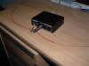
Vector Impedance Antenna Analyzer AIM4170

I did some scans of a couple of antennas, a dipole made from 19inch long hook-up wire, and a groundplane antenna (a monopole) made up using 19inch lengths of steel rod.
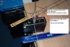
The dipole.

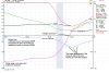
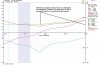
With the dipole and the antenna analyser just laying on my desk, I got the result as shown in the attachment below.
The legs of the dipole were 19inches long, this should give a resonant frequency around 145Mhz, in reality it was showing multiple resonances around 137Mhz due to the effect of the desk.

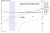
Picking the analyser up in may hand and holding it clear of the desk and other stuff, I got a totally different picture.
The general apperance was much more what would be expected from a crude dipole, the resonant frequency was higher than expected, and much higher than when on the desk.
 

Attachments

  • Dipole in air.JPG
    Dipole in air.JPG
    158.2 KB · Views: 194
  • Dipole on Desk.JPG
    Dipole on Desk.JPG
    139.2 KB · Views: 183
  • Dipole on the desk.jpg
    Dipole on the desk.jpg
    311.3 KB · Views: 236
amazing....

this instrument could be very handy to someone who builds his own antennas...usually many guys test their home made antennas directly on their transmitter with a SWR bridge.

i'll come back later on with more questions... :D
 
And now the groundplane (monopole) antenna.

I will let the pics speak for themselves.

JimB
 

Attachments

  • Groundplane antenna.JPG
    Groundplane antenna.JPG
    144.8 KB · Views: 222
  • Ground Plane Flat.JPG
    Ground Plane Flat.JPG
    133.4 KB · Views: 234
  • Ground Plane 45 degrees.JPG
    Ground Plane 45 degrees.JPG
    139.3 KB · Views: 172
  • Ground Plane optimised.JPG
    Ground Plane optimised.JPG
    134.9 KB · Views: 222
i'm back!

i did some study and some experiments...and i think i got improved a bit...
so if planning to improve the fm transmiter by myself by the way it helps alot if i imagine the antenna as a speaker and the FM transmiter as an audio amplifier...

so here's what i'm thinking to do... starting from the power supply... i'm going to use a VK200 at the power source so i can filter any noise going to the fm transmiter when i'm not using batteries..

but also i got a better idea... i'm thinking of using an lm7805 with the needed capacitors to stabilize the power supply and then use a Murata BLM31AJ601SN1L which i got available from past projects so i can keep the regulator safe from oscillations.. and keep a clean power supply for my FM transmitter.

That is a seriously poor circuit for many reasons.
The antenna is directly connected to the oscillator tank circuit, there is no way that is going to be stable, especially when someone touches any part of the circuit.


now about the antenna that is directly connected to the oscillator tank...what can i do about that??? can i use another transistor as a buffer?!

There are too many unknowns to define the impedance of your antenna.
As for the transmitter, it does not have a defined output impedance or a designed load impedance.
Any load (ie the antenna) on that circuit will shift the frequency of and untimately stop the oscillator.

antenna is a load to the FM transmiter as the speaker is a load for an audio amplifier right?

what do you want to know so you can tell me the impedance of my monopole antenna other than the length of the antenna and the frequency of my trasmiteter?

To state that the RF output from the transmitter is about 50mW is a BIG assumption which is likely to be VERY wrong.
The power output of the transmitter will be very dependant on the load presented by the undefined antenna.

antenna is a load to the FM transmiter as the speaker is a load for an audio amplifier right? so an audio amplifier that outputs 100W at 4ohm it outputs less at 8 ohm is it the same?

And now the groundplane (monopole) antenna.

i also need results from a monopole antenna without groundplane as the one i'm using and on frequencies close to the ones used on FM radio broadcasting... as do i ask too much? :D
 
now about the antenna that is directly connected to the oscillator tank...what can i do about that??? can i use another transistor as a buffer?!
I suggest that you look at the FM transmitter circuit by Audioguru on this site, it used an amplifier stage to isolate the oscillator from the antenna.

antenna is a load to the FM transmiter as the speaker is a load for an audio amplifier right?
Yes.

so an audio amplifier that outputs 100W at 4ohm it outputs less at 8 ohm is it the same?
Yes.


what do you want to know so you can tell me the impedance of my monopole antenna other than the length of the antenna and the frequency of my trasmiteter?
This is a completely pointless exercise, because...

i also need results from a monopole antenna without groundplane as the one i'm using and on frequencies close to the ones used on FM radio broadcasting... as do i ask too much?
The antenna has to have two "wires", a dipole has two wires, the second wire of the monopole is the groundplane.
An antenna without a ground connection for the current to flow through a circuit (yes, there is current flowing in a transmitting antenna), is like connecting up a speaker with just one wire.

JimB
 
I suggest that you look at the FM transmitter circuit by Audioguru on this site, it used an amplifier stage to isolate the oscillator from the antenna.

as i said before i'm aware about the FM transmitter Audioguru did...
i need someone to explain me where is that stage and how i can copy it...


The antenna has to have two "wires", a dipole has two wires, the second wire of the monopole is the groundplane.
An antenna without a ground connection for the current to flow through a circuit (yes, there is current flowing in a transmitting antenna), is like connecting up a speaker with just one wire.

interesting.. i could ask why it uses only one wire...but i thought it's similar withthe radios...

what about my ideas for improvement do you agree with them?
i'm also thinking to change the air coil with an axial inductor of the same inductance is that possible?
 
i have started a PCB based on the simple FM transmitter where i intend to make my modifications...

i will try to substitude as many components as i can with SMDs or atleast with smaller thru hole so i need to know if i can use an 100nH inductor in the place of the air coil..

The followin pcb is done on windows paint program i don't want to use any specified tools like EAGLE because i want also to be able to do my designs without any fancy tools.
 

Attachments

  • RFP.JPG
    RFP.JPG
    5.1 KB · Views: 183
In my FM transmitter I used a low-dropout 5V regulator because the voltage of a 9V battery quickly drops lower than the minimum input voltage for a 7805 regulator.
I used a 3rd transistor as an RF amplifier to isolate the tuned circuit of the oscillator from stray capacitance near the antenna.

Audio is completely different to RF. The output impedance of an audio amplifier is extremely low, 0.04 ohms or less.
The output impedance of an RF amplifier matches the impedance of the antenna to avoid high frequency reflections that cancel the output signal.
 
In my FM transmitter I used a low-dropout 5V regulator because the voltage of a 9V battery quickly drops lower than the minimum input voltage for a 7805 regulator.
I used a 3rd transistor as an RF amplifier to isolate the tuned circuit of the oscillator from stray capacitance near the antenna.

i don't have 5V low drop out... either i'm going to use 3.3V LDO or a normal 7805.. what do you think?

on the other thread you told me i can replace the second LC tank with a resistor if the transistor before the antenna is biased correctly for it...

can you explain it a bit more? why you used that LC? isn't it much difficult to regulate two LC tanks at the same values??

aproximately what value of resistor do i need in the collector so i can replace the LC tank?
 
Every semiconductor manufacturer makes 5V low-dropout regulators.

The DC current gain of a 2N3904 transistor is from 100 to 300.
With 20mA collector current and a collector resistor of 220 ohms then a base resistor of 83k will be good when the gain is 200 but not good if the gain is higher or lower or if the temperature changes. The operating point will also change as the battery voltage runs down. So the transistor must be biased properly with more resistors so that any 2N3904 transistor will work at any reasonalble temperature and at any reasonable supply voltage.

With the tuned circuit then the output is still a pretty good sine-wave when the transistor is saturated or is cutoff. Then the interference is low.
 
With the tuned circuit then the output is still a pretty good sine-wave when the transistor is saturated or is cutoff. Then the interference is low.

hi!

still i haven't understood the purpose of the second LC tank...

can you check the modifications i did on the schematic?
 

Attachments

  • fm.jpg
    fm.jpg
    21.3 KB · Views: 183
Last edited:
The second LC tank allows the output to swing below ground and above the supply voltage with low harmonics. Your second transistor with its poor biasing might be saturated or might be cutoff (a clipped sine-wave) which produces severe interference harmonics.

I don't know which adjustable regulator you are using.
The output transistor needs to have its own supply bypass capacitor, or remove the choke.
Your audio does not have pre-emphasis so it will sound muffled without treble audio frequencies when played on an FM radio.


can i "play safely" without the second LC tank? if yes show me how...

the regulator is the reg102-A it's an ultra LDO which i had also available.. but at first i didn't wanted to use because for the purpose of my experiments i'm trying to utilize old used spare components and that regulator is new.. i guess it's also too much for that circuit..


btw the ferrite bead is that type "Murata BLM31AJ601SN1L" it's what's left from an old project of mine...are they suitable for my design?!


right now i don't care so much about the audio quality...mostly i'm trying to make it as stable as possible and learn something from it. ;)
 
can i "play safely" without the second LC tank? if yes show me how...
Simply remove the horrible 83k biasing resistor and replace it with a 47k negative feedback resistor from the transistor's collector to its base. Then a low gain or a high gain transistor will not clip and produce interference harmonics. But the negative feedback will reduce the output level.

the regulator is the reg102-A
Datasheetarchive.com does not know your regulator or its part number is incomplete.

btw the ferrite bead is that type "Murata BLM31AJ601SN1L" it's what's left from an old project of mine...are they suitable for my design?!
I didn't look for the datasheet of the inductor because it is not needed.
 
Simply remove the horrible 83k biasing resistor and replace it with a 47k negative feedback resistor from the transistor's collector to its base. Then a low gain or a high gain transistor will not clip and produce interference harmonics. But the negative feedback will reduce the output level.

great! thanks!! :):)

ok no prob audioguru.. as i told you this project is done so i can learn a bit of RF and gain some more experience doing my own PCB designs with SMD components so i don't mind about the reduced output level nor the not so great sound quality!!! but i mind it's stability which makes it worthless to play with it. ;)

but i want to know how i can calculate the power output, if you check the last post on the first page you'll see that i tried to calcuate it but JimB stopped me by telling me that it's a "big assumption"... that's why i wanted to know the power output of your transmitter.
 
Last edited:
i did this pcb... based on the schematic on my last post..there are some changes mostly around the regulator that i haven't included to the schematic
any comments most appreciated! :)
 

Attachments

  • RFPCBA.jpg
    RFPCBA.jpg
    8 KB · Views: 188
audioguru i think my regulator oscillates... firstly i tried an adjustable and it was also oscillating now i'm using reg101-33. At the input there is one 100nF and 100uF at the output. i wasn't able to locate the frequency on the radio so i'm getting harmonics and i hear a high pitch sound...the voltage on the regulated rail is 1,65V it's lower than it should, at first i thought it is voltage drop because of the load but you can't hear your voice on the radio... the electret mic doesn't do anything unless you hit it or blow hard on it

i have changed your resistor values on the oscillator from 47k to 22k and 10k to 4,7k so it can be able to work on 3.3V.


help? :rolleyes:
 
Last edited:
audioguru i think my regulator oscillates... firstly i tried an adjustable and it was also oscillating now i'm using reg101-33. At the input there is one 100nF and 100uF at the output. i wasn't able to locate the frequency on the radio so i'm getting harmonics and i hear a high pitch sound...the voltage on the regulated rail is 1,65V it's lower than it should, at first i thought it is voltage drop because of the load but you can't hear your voice on the radio... the electret mic doesn't do anything unless you hit it or blow hard on it

i have changed your resistor values on the oscillator from 47k to 22k and 10k to 4,7k so it can be able to work on 3.3V.
help? :rolleyes:

hi,
Ref your PM.

We need a datasheet for the voltage regulator before we can advise.

At a first look, its the Vreg area thats a problem.
 
I have never seen the texas Instruments low dropout regulator.
they show it with no output capacitor, 1uF and 10uF. They do not show what happens with a 100uF output capacitor. Try a 1uF output capacitor.
 
Status
Not open for further replies.

New Articles From Microcontroller Tips

Back
Top