Continue to Site

Welcome to our site!

Electro Tech is an online community (with over 170,000 members) who enjoy talking about and building electronic circuits, projects and gadgets. To participate you need to register. Registration is free. Click here to register now.

  • Welcome to our site! Electro Tech is an online community (with over 170,000 members) who enjoy talking about and building electronic circuits, projects and gadgets. To participate you need to register. Registration is free. Click here to register now.

Another lead acid battery discussion

Status
Not open for further replies.
Yea, I can do that. It won't be too far off from what I have above but for all the help I get from the many forums I have visited over the years, I would think that is the least I could do. I might ask that people post to let me know if they use it though so that I know I have done some good in the world.....;-)

I was just tweaking it on the bench again but have to go do some outside stuff so will put it off for a few days.

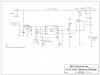
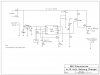
I am not sure that Mosfet will take the power,..

In looking at the data sheets, it is rated for 200 watts at ambient temp of 25C. I figure typical hard charging rate will be max of 10 amps and it will be dissipating about say 18 volts-about 9 volt (battery value, very low batt) so 9v*10a=90 watts. ....and this is a pulsed value, sort of (rectified full wave). The math says it is OK, if I am reading the data sheets correctly but it seems like a lot for a T220 case....what do you think?

I will try it anyways as I have quite a few of them but perhaps I should look for one in a T03 case? I have limited experience with actually evaluating case vs power dissipations and have never really had to consider the numbers before. I usually have just replaced what I took out.
 
Cool.

The FET will be ok. It is turned on hard so there is very little voltage drop across it, So it is I sq R. or .025 X 100 or only about 2.5 watts. It will need a little heat sink but only a few square inches of surface area. Maybe 20 square cm. That will keep it at 50C or so. Same or a bit bigger (2X) for the big diode.
 
I have a bit of a glitch. In connecting the circuit to a battery and running off the charger, as the schematic is, I find that the voltage at the junction of R4 and 3 is 1.7 volts (much to high to enable charging), as it is seeing the charging voltage at the top of R3. I suspect that since the neg of the battery connects to the circuit only through Q1, it is not a part of the circuit till Q1 is on, but won't be on if cct is seeing open cct charging voltage (19+ volts)
I need to get the reference voltage but not connect the battery to ground....perhaps the mosfet being part of the neg lead is not a good idea....? Looked odd to me but trying to work with what stock I have....

Suggestion? I will look at moving the mosfet but to turn it on, I needed to have the source at gnd potential so having it in the pos lead is not possible, (I do not think) so perhaps it is the wrong component for this application?
What do you think? Am I missing something here?

I have attached a quick fix (read very quick sketch up) .....which I think will work since the charger voltage is substantially higher than the battery voltage.... but then upon connecting them, they become the same so, if so, how can I turn on Q1 in this circuit? Perhaps the only solution is a depletion fet?
 

Attachments

  • Charger.jpg
    Charger.jpg
    60.3 KB · Views: 150
Last edited:
High side switch

Thats right you want to check it before charging.
If you are going to switch the high side a P FET is probably the easiest way to go.
Here is a schematic for a high side switch.
Another thing to think about is the ripple on the battery voltage. How do you plan to terminate the charge?
Also note the short glitch at turn on. This is from discharging the filter cap in the logic supply. Might want to "work around" this in your software.
If you want to PM me your address I'll drop a couple of FETs in an envelope. I've got a tube of IRF4905's.

That schematic looks good! The only thing needed is a small resistor on the gate to protect the micro in case the transistor shorts out. It would make the mosfet a little slower, but that won't hurt much.
 
Ron, thanks for the offer of sending me some. Very kind of you but I can order some up if I need to. I would rather try to figure out how to use up some of my stock (picture someone beating their head on the wall...;) )

I have some power PNP's around here. What about using one of those? ie MJ4502 has a gain of 25-100. At 10 amps max charge rate, and a gain of 25, that means Ib of about 400 mA so Rb would have to be about 10 watts min but otherwise, would this work? Q1 would be on in saturation, if I do it right, so again, not much power dissipation, if I am correct....?

Twister, thanks for the input. I guess you are referring to Ron's diagram, not mine?..;-( yes, I am learning to trust Ron..

I will add the resistor to the gate leg in all my mosfet circuits now...good point. Never thought of a short situation. 1K? Thanks


Again, reasoning OK?

I also have 2sb337, ecg393, which have adequate collector current ratings...
 

Attachments

  • Battery Charger May 16.jpg
    Battery Charger May 16.jpg
    87.2 KB · Views: 183
  • PNP Dar MJ4502.pdf
    56.8 KB · Views: 207
Last edited:
The MJ4502 would work but if you look at the specs it drops 2 volts at the Hfe of 25. That would put the power dissapation at 20 watts which would want a Big heatsink. You could probably get away with say 600 ma of base drive and a .3 or .4 volt drop. I just noticed the 6 volt switch which brings up 2 things:

1- The current will be much higher at 6 volts. Is your transformer good for it? If so we need to shoot for more like 15 to 20 amps. This drives up the base current even more.

The FET is a much better implmentation just because of the power losses.

I modifies the simulation to reflect my guess at the 6 volt circuit.

I also change the 1K resistor to 10k and added a 15 volt zener so the gate voltage will be high enough to run from 6 volts.
 
Hmmmm....I can play around with the base resistor. And realistically, whenever I have connected a low battery ie 50%ish, to a charger like this (built in ammeter) the charging current drops pretty quickly like in minutes so charging current would typically be 5-6 amps for the majority of the time.... but, of course, we need to design in the "what if " factor though if it is to be reliable.

As for the 6 volts, the transformer has 3 inputs on the primary...12 volt@10 amp, 12 volt @ 2 amp and 6 volt @ ..(I forget) but that is how it accomodates the reduced voltage. My switch is just to tell the microcontroller to use different values for charge control. I was trying to figure out how to detect the switch position automatically but since it is on the primary side, I was not sure how to do it. That would be a goochie add on...;-)

For now, the switch (microcontroller one) and maybe software to detect a really low battery ie that which is most likely 6 volts would work ....I want to get it working first then play with those add ons.

Funny...I was supposed to be working on another circuit that lead me to this one which moved me to a 3rd project and I still have not finished the first project....I wanted to get a better handle on battery chargers anyways so it is all good.

Back in the beginning of this thread,(see post#20) I was asking how the charge current is controlled in these "dumb" chargers and it was mentioned that it is a function of the battery, transformer and rectifiers, a "tight" circuit so that is what I am counting on. The only real control I put on it is to reduce it when battery reaches about 80% and stop it when battery reaches 100%.
winding side that

You are causing me an interest in "Spice". I do not know this program but have heard of it and it looks interesting for running simulations. Is this a trial version or demo or do you have to buy it?
 
Last edited:
Ahh. I see.
It would be a good idea to know the peak voltage and the spec'd current at the 6 volts tap.
Absent that a 20 ohm 10W for the base resistor should do it for the 12 volts. Lets figure 8 watts lost thru the transistor. (.8 volts @ 10 Amps)
So to keep the transistor at 50C we need a heatsink of about 3 degrees C per watt. Thats about 45 square inches of surface area. Pretty big. Does the old charger have a big heatsink?
We are going to have to do some experimenting to get a feel for the transformer. Also keep in mind you don't want to charge a 25 Amp Hour battery with 10 Amps. So all those taps will come in handy.
I agree the 6 & 12 volt thing can be worked out once the basics are working. Wish you had a scope.
LtSpice is a free down load. Just google LT Spice download. It won't do it for you and it won't protect you from running a part outside the spec, but it does help get a good feeling for functionality.
 
Who said I don't have a scope....? I just don't turn it on very often unless I am tuning an ultrasound unit. Other than that, it ...collects dust? ;-)

I did record some DVM RMS values earlier but will have to go look for them. I don't think they would be too relevant as they were open circuit and used to help me to determine which taps belonged to which switch positions so that I could wire the 6volt/12 volt switch back in...( I probably pulled the wires off years ago, thinking I was going to scrap this old battery charger....who would have thought I was going to spend days verging on weeks trying to revive a $30 charger......lol )

So....what should I look for and I will go check and get back to you....although later. I am winding down now and enjoying a glass of vino and the daily paper....

Correction, I read your post again...the spec'd current for the 6 volt tap is 10 Amp. It is an old Solar charger that I cannot find info on right now. RMS voltage on the 6 volt setting...I will get back to you.

Heard the email come in so thought I would look. You are providing my most interesting emails right now....;-) or :-( depending on how you look at it.

Thanks and Cheers,
 
Last edited:
On your advice, I ordered up some irf4905's ....and some ndp6020's. If I understand correctly, the 6020's can be driven directly from a microcontroller ie full on at 5 volts (or zero in the p channel) and off at the opposite, yes?

With Digikey, I will have them tomorrow...pretty good service here in Canada with them.
 
Ron

How does this look for output control?

Q2 will be a 2N7000 or similar, depending on what I have in stock. Maybe pull down resistor needed on pin 5? 1K value typical? I am thinking to prevent false triggers?


How does the rest of the cct look? See any glaring errors or poor practices? It seems to work, under test conditions, but wondering if you or anyone would have any suggestions?

I added a resistor to the controller output too, as seen in the schematic only.

Thanks

I liked your first schematic here. You could drive the output transistor directly from the micro. if you exchanged it for a low on transitor, or if you put a pull up resistor on the gate and changed your micro to sink the voltage instead of sourceing it. I have no idea how you do that because I know very little about micros. You need to put a gate resistor on the base to protect the micro. in case it shorts. A 1K would work , like you said in your other post. Also you have to move the sense ground on R4 to the battery negative. The drain needs to connect to the battery negative, and the source to the charger ground. In the second schematic it looks like you have it connected to the positive, which will not work. Does the micro. put out a steady voltage or a pulse? I know that you are already going to use some P channel mosfets, as in ronv's schematic, but I have a lot of N channel mosfets and I want to make this circuit one of these days. I have been wanting to learn about micros anyway. Why did you choose the NANO8?
 
On your advice, I ordered up some irf4905's ....and some ndp6020's. If I understand correctly, the 6020's can be driven directly from a microcontroller ie full on at 5 volts (or zero in the p channel) and off at the opposite, yes?

With Digikey, I will have them tomorrow...pretty good service here in Canada with them.

The ndp6020's looks like a great choice for your final! Very low on voltage required. I'm thinking that would work great without a driver. I need to get some of those too.
 
Hey Twister, thanks for the input. The micro puts out what ever you need and in my case, I set the output full on (whether that be zero or Vcc level depends on what I am driving) for a full charge rate. When the micro detects a battery voltage=80% of what I consider a full charge (14.3ish for a 6 cell battery) then the output becomes a pulse train, with a 20% duty cycle, (pulse width modulation), reducing the charging rate and this continues till the battery voltage reaches the 100% level. Then the output goes full off but the micro will check the battery continuously or occasionally, depending on what I set, ie hourly,every minute or continuously, and should the voltage drop below the 14.3, then it will enable the charge rate at 20% again.
That is my theory, mostly from what I learned in this thread as to how the battery should be charged. I am relying on the original battery charger transformer and rectifiers and cct protection (a built in cct breaker) to limit the current. ie I am not controlling charge current nor monitoring it. I only say full on, 20% on and off. This is a retrofit to an old charger so I did not start from scratch to build a charger.

As to choosing the Nano8, I stumbled across Basic Micro line and the pricing on them looked reasonable. I am familiar with the old BASIC Stamp and have an old Atom stack around here but never really used it. I am hoping to move into Pic's directly one day but for now, I am happy with a $3 chip. The programming software is free and relatively easy to use. The guy who owns the company or at least who I corresponded with a few times seemed pretty good (helpful). I have used some of the larger Nano's too driving an LCD display and doing some experimenting and they seem to work well. I thought the Arduino series was much more expensive than I have found lately so I must have been looking at some the more powerful ones. I have noticed that there is not much chatter over on the https://www.basicmicro.com/ forum though. Nathan (owner) said he has sold a lot of chips so I guess that those buying them don't ask as many questions as me....;-) He is the one who answers my questions most of the time, although a couple of others chime in occasionally. They might have more discussions in the other sections.
 
Last edited:
Hey Twister, thanks for the input. The micro puts out what ever you need and in my case, I set the output full on (whether that be zero or Vcc level depends on what I am driving) for a full charge rate. When the micro detects a battery voltage=80% of what I consider a full charge (14.3ish for a 6 cell battery) then the output becomes a pulse train, with a 20% duty cycle, (pulse width modulation), reducing the charging rate and this continues till the battery voltage reaches the 100% level. Then the output goes full off but the micro will check the battery continuously or occasionally, depending on what I set, ie hourly,every minute or continuously, and should the voltage drop below the 14.3, then it will enable the charge rate at 20% again.

This is a very interesting project that you are building. I learned a lot from that battery university link. You now have the first two stages programed. The 14.3V would be the topping stage. I know that my batteries boil at 14V. You can remove the top of the battery to see if it is boiling. Be careful of sparks while you are charging at that voltage. The battery can explode! I guess it would be simple to add the third stage of a float charge if you wanted.

That is my theory, mostly from what I learned in this thread as to how the battery should be charged. I am relying on the original battery charger transformer and rectifiers and cct protection (a built in cct breaker) to limit the current. ie I am not controlling charge current nor monitoring it. I only say full on, 20% on and off. This is a retrofit to an old charger so I did not start from scratch to build a charger.

As to choosing the Nano8, I stumbled across Basic Micro line and the pricing on them looked reasonable. I am familiar with the old BASIC Stamp and have an old Atom stack around here but never really used it. I am hoping to move into Pic's directly one day but for now, I am happy with a $3 chip. The programming software is free and relatively easy to use. The guy who owns the company or at least who I corresponded with a few times seemed pretty good (helpful). I have used some of the larger Nano's too driving an LCD display and doing some experimenting and they seem to work well. I thought the Arduino series was much more expensive than I have found lately so I must have been looking at some the more powerful ones. I have noticed that there is not much chatter over on the https://www.basicmicro.com/ forum though. Nathan (owner) said he has sold a lot of chips so I guess that those buying them don't ask as many questions as me....;-) He is the one who answers my questions most of the time, although a couple of others chime in occasionally. They might have more discussions in the other sections.

It's probably best to stick with what you allready know and have experience with. I still don't know which micro to start out with.
 
Charger

I made a couple of changes.
I think I had added the zener before just in case your input voltage is above 20 volts. I also made the gate drive resistors a little smaller to speed up the FET for your PWM.
I took out the big diode because it didn't really protect from a reversed battery. But, I added a small diode to clamp the a to d input to prevent it from going much below ground if the battery is reversed.
I also scaled up the divider to give a little better resolution and added a filter cap so you can measure average voltage. You could probably do lots of samples with the micro and average them but it's only one part.
I added Twisters resistor.

Does the voltage switch acually switch the primary taps? I trying to figure an easy way to select the range. Maybe opto-isolaters?
 
Thanks Roltex....I think I might even have some of those around here but have never used them. I am so far into this project now I will continue on to see it through but might try the BQ2031 in another charger.

Ron, yes, the switch switches the primary. There are four connections on the primary, one common and three others. Very specific to this charging unit I guess.

I have the circuit working. Occasionally, the microcontroller hangs up so I will research that a bit more, but otherwise, cool!

I was struggling with the mosfet configuration a bit. I am much more comfortable with NPN's and PNP's so biasing a P channel mosfet was kind of confusing. I think I have it. I like to think in terms of conventional current flow (pos to neg) so in a P channel, current flow is source to drain, yes? whereas in an N channel, current flow is drain to source.....? And to bias it, I need to set gate low relative to source for P channel and high for N channel, .....? So to simplify, gate voltage is always relative to source kind of like base to emitter, I guess. Sounds like the source equates to the emitter and the drain equates to the collector?

I googled up some tutorials but only skimmed them. I probably just need to sit down and do up some circuits.....

I have it running now and will wait for battery voltage to come up to see if it shuts off OK. I could go change the value in software too, I guess but battery needs a charge as I need it this weekend...;-)
 
I always just look at FETs as voltage controlled transistors, but I have trouble with current flow. :eek:
 
Status
Not open for further replies.

Latest threads

New Articles From Microcontroller Tips

Back
Top