Continue to Site

Welcome to our site!

Electro Tech is an online community (with over 170,000 members) who enjoy talking about and building electronic circuits, projects and gadgets. To participate you need to register. Registration is free. Click here to register now.

  • Welcome to our site! Electro Tech is an online community (with over 170,000 members) who enjoy talking about and building electronic circuits, projects and gadgets. To participate you need to register. Registration is free. Click here to register now.

Another lead acid battery discussion

Status
Not open for further replies.
Colin, as you suggested, I googled up "gassing voltage" and found a few links, this one seems to be most relevant to my questions.

https://www.powerstream.com/SLA.htm

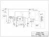
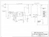
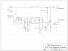
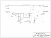
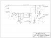
I started out with the flow chart for a control circuit. What you think....?

Start- check battery voltage-battery voltage=<11 volts?>yes>full charge rate
no>bat voltage=<13.8v?>yes>20%charge rate
no>disable charge>goto Start

Does that sound OK, keeping in mind that I will be using the transformer and rectifiers (and over current protection, aka circuit breaker already built into charger) from the original battery charger, therefore staying within the parameters of the "tight circuit" you describe above? I thought I might also add a loop whereby we check for a short, ie voltage less than ~2 volts or so, which disables output....

What do you think?
 
Last edited:
Some of the automatic chargers will not start to charge if the battery voltage is very low. This is very anoying.
Sealed Lead Acid batteries have an extra metal added to the plate composition to increase the internal voltage before gassing occurs.
This is why they can be sealed and do not start to gas during the charging process.
 
If you're designing a smart controller that regulates and controls the battery charging voltage a good thing to have that's not seem on most units is remote voltage sensing (where the voltage measurement that controls charging is not inside the charger but at the connectors that clamp the battery terminals. This makes it possible to automatically adjust for I/R voltage losses in the wiring as the current changes during the charge cycle. It's a very good thing to have if you wish to fast charge SLA batteries at the highest voltage but not to start gassing. (a fast way to reduce SLA battery life)

https://en.wikipedia.org/wiki/Four-terminal_sensing
**broken link removed**
 
Last edited:
I have the programming done and the circuit drawn up and sort of built. I am using a 5 volt supply for the ucontroller and using a separate variable supply to simulate the 12 volt battery, thereby switching modes (full charge, partial and off) easily. It all works fine so tonight, I wanted to switch the Mosfet on and off. Till now, I have just been checking the output (Pin7 in this diagram although that has since changed) by monitoring D1 and a DVM.

I am having a problem turning the Mosfet (Q1) in the attached diagram on. In my test circuits, I have connected the 5 volt ground and the variable supply ground together. In the final circuit, of course, the 5 volt supply is part of the 12 volt supply so it is a non issue.

Any ideas why the mosfet might not switch? The mosfet is an IRF59ND.... https://www.electro-tech-online.com/custompdfs/2012/05/irfb59n10dpbf.pdf
It is a Hexfet and I am not sure what that means exactly. Off to google that I guess but will it not function as a normal Mosfet in this application?

Specs state Vgs of 3-5.5 volts will switch it and it is getting 4.8ish from the uContoller. I checked the D to Gnd and measured 12 volts (through the lamp) I also measured 12 volts from the source to the 12 volt positive so the wiring checks out.

I am no expert with Mosfets but did think I was getting a handle on them in this simple application but.....?

Thanks,
Shawn
 

Attachments

  • Battery Charger bmp.jpg
    Battery Charger bmp.jpg
    111.7 KB · Views: 165
You need a logic level FET. This one has a gate threshold voltage of 3 to 5 volts but only at 250 ua.
 
Ahh. So perhaps switch it with another fet switching the 12 volt ...?

I just ordered from Digikey and so was going to for awhile. Besides I have a few of these and small fets so can add one more component....I will redraw and send an updated schematic
 
Ron

How does this look for output control?

Q2 will be a 2N7000 or similar, depending on what I have in stock. Maybe pull down resistor needed on pin 5? 1K value typical? I am thinking to prevent false triggers?

How does the rest of the cct look? See any glaring errors or poor practices? It seems to work, under test conditions, but wondering if you or anyone would have any suggestions?

I added a resistor to the controller output too, as seen in the schematic only.

Thanks
 

Attachments

  • Charger and test cct jpeg.jpg
    Charger and test cct jpeg.jpg
    65.9 KB · Views: 160
  • Battery Charger jpg.jpg
    Battery Charger jpg.jpg
    116.3 KB · Views: 160
Last edited:
Move the 1k (R6) to the drain side of the FET and take the gate signal from there. You will need to invert the signal in your micro. Right now it is a source follower ( kind of like an emitter follower) so won't work. There are versions of the 2N7000 that switch at a lower voltage that would be better, but the 2N7000 will probably work. If to have to order one look for the lower gate threshold voltage. Let me know if you have trouble finding one and I'll check it when I get back from golf.;)
 
Like this?

I will not be able to get back to making the changes in the cct but will report back if this is what you are thinking.


Thanks,

Hope your golf went well. My neighbour winters in Arizona and just got back from there.

Cheers,
 

Attachments

  • 6_12 Volt Battery Charger.jpg
    6_12 Volt Battery Charger.jpg
    116.9 KB · Views: 148
Last edited:
Ron

I made the changes today and it works well.

Thanks

I think I am almost ready to put it to a real test ie a battery instead of a test cct.... I am having a hard time getting the uC to recognize the switch change on P3 and am finding the controller occasionally stops but perhaps some filter cap's might help. As to the programming, I have been over at the basicmicro forum asking about the software.

Thanks
 
Could be switch bounce. Make R5 a 15k and add a 1 Ufd. from p3 to ground or add a delay in software and sample it twice.
 
No, even if I tie it to Vcc or gnd, it still only reflects gnd....zero. I have to play around with that parameter (IN3) ...maybe I am not clear on how it is used....or maybe that input is not good...will try another chip or make a test cct.

I submitted the code and schematic on the Basic Micro forum and hopefully someone can tell me what it is that is wrong. As I type this though, I am thinking it is so simple that it is most likely the chip.

I will report back later. :)

Thanks
 
Hey Ron

I am looking for your opinion.....I was wondering what the effects of the pulsating DC will have on the operation of the Mosfet Q1. Q2 will be on 100% as it is driven from the filtered 5 V but the Drain of Q2 feeds the pulsating 12 volt supply to the gate of Q1. Should it be OK or should I be putting a filter cap in the gate of Q1 (say 1000 uf?) to provide a more constant gate threshold voltage? I was also thinking of a diode in the drain limb of Q2 so that a heavy charging current would not draw down the cap. I made the changes in the attached diagram.

Re the uC not seeing my switch input, apparently there is a glitch in the firmware. Another user wired up a test circuit and the Nano would not see the input state change but it works fine as an output so I will just switch two of the I/O's. They will fix this glitch in the next upgrade, I am sure.

If interested, ...**broken link removed**
 

Attachments

  • Battery Charger.jpg
    Battery Charger.jpg
    120.3 KB · Views: 160
Last edited:
I think the 2200 Ufd. back at the regulator will hold the voltage at about the battery voltage so you probably don't need anything else. Do go back to the schematic in post #29 though. You will need to "flip" the LED and tie the resistor to +5 so it will still light while charging.
 
One other thought. Might be better to measure the battery voltage on the battery side of the diode so its voltage drop won't be a factor.
 
I think I can do that in the software with the threshold values I choose. I do not want to subject the uc to a reverse voltage should battery inadvertently get connected backwards.

Yes? No?
 
Sure, I guess we are not building a million of them. ;) There might be a slight error by battery type as the diode drop varies a little with current. I'm guessing you are setting the termination voltage at 14.3 or so?
 
Yea, 14.3 sounds reasonable. Honestly, I had not made that decision yet. I have been concentrating on getting the circuit running, knowing that value is easy enough to change once the hardware is in place. I started typing a long explanation here and referred to the gassing voltage charge here https://www.powerstream.com/SLA.htm but then when I started considering common temperature situations for my climate and when I would most likely be using it.............., I ended up around 14.5 volts as a reasonable compromise. :) I had to do some reasoning and reading to come up with what you already knew....;-)

The charger charges at the full capabilities of the charger transformer and battery till about 10 volts, as measured, then drops to about 20% charge rate till 14.5 volts is detected, then stops charging. It monitors the voltage and will start charging again, should the voltage drop. Although, if my final voltage is going to be around 14.5 volts, then 80% would be more like 11.6 volts so that may be my value to switch to a lower charge rate. The 10 volts I think was just a number I grabbed for the test bench.

Well, as I said earlier in this thread, this adventure was more about learning about these chargers and charging L/A batteries, doing a microcontroller project and the associated programmming, etc. than about saving an old dumb charger and I think that mission is going well. I still have to move the cct to an actual battery and see how it goes,,,:eek:. Then install it in the old battery charger case etc. I guess I might as well make a few cct boards since I have a few dumb chargers that could benefit from this upgrade.

Thanks again.
 
Let us know how it comes out. Maybe you could post your circuit and code for others when it is all humming..;)
 
Status
Not open for further replies.

Latest threads

New Articles From Microcontroller Tips

Back
Top