Continue to Site

Welcome to our site!

Electro Tech is an online community (with over 170,000 members) who enjoy talking about and building electronic circuits, projects and gadgets. To participate you need to register. Registration is free. Click here to register now.

  • Welcome to our site! Electro Tech is an online community (with over 170,000 members) who enjoy talking about and building electronic circuits, projects and gadgets. To participate you need to register. Registration is free. Click here to register now.

Another lead acid battery discussion

Status
Not open for further replies.

ShawnR

Member
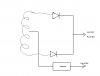
I have looked (albeit quickly) through some of the previous postings re battery charging. I am looking for a bit of explanation as to why these battery chargers go from super simple to super complex. (I am guessing just features, ie charging rate, charging shut off, although I struggle with this one...later coment) I have a few old battery chargers, typical automotive ones, 6 Amp and 10 Amp. The circuit board in one (10 Amp, 6v/12v) was removed several years ago (burned...given to me this way) It consists of a center tapped transformer and the primary is switched (to accomodate the slow current charge or 6v or 12 volt, I assume)

I have bypassed the cct board for testing so essentially, full wave CT rectifier and measured 12.6 volts with the primary taps I selected. I then connected a small lead acid battery (measured 9.6 volts before any charging) and the output then measured 15 volts. I expected it to increase gradually as battery charged....? Also, the ammeter in the charger indicated only about 2 amps....I expected more charging current due to differential so can someone give a brief explanation as to why voltage across battery increased immediately (meter averaging? ) and current is so low (is there a higher impedance in small batteries that limit current?)

The original cct bd was simple...cannot recall components and some were burnt beyond recognition but I am guessing a large SCR or transistor and a few small discrete components. Some of the circuits I see posted here ie Guleph cct (**broken link removed**), look quite complex. Any suggestions for a simple charging cct? Can I just switch (via Mosfet or transistor) the rectifier output to the battery till battery voltage comes up, assuming I have to stop charging to monitor voltage. This as a result of my tests today indicate that the battery voltage appears higher during charging than the actual battery voltage is? So, it becomes charge, stop and check voltage, if necessary, charge...repeat. If not necessary, just monitor voltage.....?

I have ventured into uControllers a little so thinking of using one but it seems overkill considering the original cct in this box.....and leads to including a +5 supply for it, etc, so simple gets complicated. I guess it is true that "simple problems bring complicated solutions" ....;-)

Why is overcharging protection needed?....I would think that if a charger put out say 13.8 volts, then the battery charging current would gradually decrease until virtually zero as the battery voltage approached the max of 13.8 that the charger put out....why does it overcharge? I know it does/can with out protection, but why? or is this only in the case of simpler chargers which may put out more voltage?

Looking forward to the comments.

Thanks
Cheers, Shawn
 
Last edited:
1. The previous cct had only one diode - you have two.
2. If the voltage rose immediatley, the battery is faulty.
3. Read-up about sealed lead-acid batteries and the "gassing voltage. "
 
Thanks nsaspook for the articles. They did help.

Colin, what cct do you refer to? "1. The previous cct had only one diode - you have two. "

As for faulty battery, maybe...I will put it on my "fancy" charger and see what it tells me about it. Being that it is an old ATV battery, was so low in storage voltage and reacted to the charger as indicated, sounds like it is defective. I will try some other batteries around here to see what happens. Kind of making this into a Battery Charging 101 course, which I could use. Thanks


I am now thinking that if I am to take the time to repair these old chargers anyways, maybe a little uController and set some charge levels would be a worthy project....?

Thanks
 
Interestingly, I put another (larger lawn tractor battery on the "charger", which right now is just a transformer and 2 diodes. The battery voltage before connection was 12.5 volts or so and as soon as I connected, it became 16 volts so it looks like the battery acts like a capacitor? in that it is showing a higher voltage, and the current flow into the battery was about 6amps so,.....A battery with a higher cca and higher starting voltage drew more charging current....not what I would have expected. I would have thought that with a higher initial charge on the battery, the charging current would have been less. So the size of the battery contributes to the actual charging current?

When I connected the first battery mentioned in this thread to the "smart" charger, https://www.canadiantire.ca/AST/bro...tery+Charger+with+Express+Start.jsp?locale=en, the voltage displayed was 11.9 so quite different than what I was measuring with my meter on the "dumb" charger. :)

So if I am to build a circuit to replace the old one in the charger, it does need to limit the output voltage during charging? I would have thought the battery would take care of that. Would you put a capacitor in the output cct similar to a power supply? I would not have, thinking that I do not see them in chargers as I do in power supplies but perhaps that is what the circuit board did in there, limiting the peak voltage out? One of the articles touched on peak values but I have to go back to look at it again.

Am I getting there? ;-)
 
I think you are getting fooled by the measurement method. While your output is DC it is pulsating DC. Take some measurements with and without the battery on both AC and DC. And before and after the bridge.
 
Last edited:
The 16v battery is faulty.
Try a known GOOD battery
You said your circuit had a bridge - this is 2 diode-drops and will deliver less current. A centre-tapaped arrangement is one-diode-drop and will deliver a higher current.
A capacitor is not needed.
It was only neeeded in SCR circuit to provide DC for the controlling circuit.
The only way to measure current is via the voltage across a 0.1 ohm resistor.
 
Ronv, that is what I was wondering too so I checked again and with different meters...I measured the battery voltage to be 12.8 volts and charger output (no battery connected) to be 13.8 volts....all sounds good. Then when I connect the battery to the charger, the voltage as measured across the battery terminals (or charging clamps) is 16.1 (and it sounds high (audibly) from the battery so I never leave it more than a few seconds.

Would a "good" charger put out a smoother waveform? akin to a power supply output? I measured the output on the smart charger with a DVM and it was about 13.7 whereas the display indicated 13.5 so well within what I would expect. Anyone know what these smart chargers do to the output with regards to how much filtering?

I have another (a third one) similar to the dumb one discussed above https://www.canadiantire.ca/AST/bro...Automatic+10+2A+Battery+Charger.jsp?locale=en. I put it on another battery (bat volts =12.9) and the measured charging voltage was over 16 as well. Either that charger is screwy too, although I have considered it a back up (till now) or that is what these chargers charge at, which I find hard to believe.They would have cooked a lot of batteries, no? Maybe I am chasing my tail but as I mentioned, the battery sounds like it is bubbling inside so it backs up the high voltage readings.

These old chargers (meaning this type of charger) have been around for years and I think worked fine, so I want to know how they work....or are supposed to work :confused:

Thanks
 
Last edited:
Colin, I guess I was typing same time as you.....no bridge in my charger, just the two diodes and center tapped transformer. As mentioned in my posts above, I have tried a different battery and same result. I also used a 2nd charger on a 3rd battery and similar measured results (unless that one is defective too, in some way, although IIRC, it has the circuit board in it and has worked in the past. Totally different battery too.
 
1. Remove the filler caps and if you see one cell bubbling more than the others, it is faulty.
2. Some smart chargers put out very high pulses to get rid of sulphating, so AC pulses are not a problem.
3. Most simple charger must be turned off as they still deliver a current when the battery is charged and it will eventually dry-out.
4. Read up on gassing voltage for the batteries you are charging to see what type of charger you need if you want to keep the charger connected.
5. Are you measuring the voltage with a $10.00 analogue meter? You should.
 
Last edited:
Measure the AC voltage comming from the transformer before the diodes.
 
I put it on another battery (bat volts =12.9) and the measured charging voltage was over 16 as well. Either that charger is screwy too, although I have considered it a back up (till now) or that is what these chargers charge at, which I find hard to believe.They would have cooked a lot of batteries, no? Maybe I am chasing my tail but as I mentioned, the battery sounds like it is bubbling inside so it backs up the high voltage readings.

These old chargers (meaning this type of charger) have been around for years and I think worked fine, so I want to know how they work....or are supposed to work :confused:

Thanks

The charge rate on those models are pretty low compared to the Ah rating of a large (car) battery so even when connected all day with higher than normal voltages no permanent damage will happen normally other than water loss from gassing. For an application that will cycle the battery down to say 50% charge every day then recharge having a smart charger that gently recharges in the most efficient matter possible is important but for a car battery that only supplies a high peak cranking current for a few seconds and is almost never discharged more that a few percent a simple dumb charger is just as good.
 
The battery that is there now is no maintenance so I cannot look at cells.
I dug out my old Radio Shack VOM and it shows similar values as the DVM's, maybe 1 volt less
The AC voltage at the Diode Anodes is 29.8 volt and using the center tap, of course, 1/2 that so 14.4ish. this is the primary tap of the transformer that I suspect yielded the 10 amp 12 volt charge (switch has been disconnected years ago too...:-( )

I put the small ATV battery back on after giving it a full charge on the smart charger. All cells bubbled pretty fast (ie shortly after connecting charger) The starting voltage was about 12. 8 (so it probably is no good as I just took it off charge a few hours ago) and it started climbing quickly but I disconnected it when cells started bubbling.

I am off to find a better battery..maybe I am just chasing bad battery problems after all but I am learning a lot along the way....thanks to you guys and your questions/answers....:)

My question is still though, does the circuitry in these simply stop the battery charging when it gets to a "relatively" full charge or does it manipulate the charging current all along, ie cutting off peaks or such? I am starting to think not which means if I can put a good battery on this charger (which has no control circuit in it whatsoever right now) it should work fine (as long as I watch it) I then have to decide how I am going to determine full charge or even 80% charge as one article suggests, then reduce the charging current....

I still have to go read something on gassing voltage (next on my list)

Thanks all
 
Thanks nsaspook. I posted the last one before I saw your posting.
The batteries I have been referring to so far have been one ATV and 2 lawn tractor batteries. I have not lugged a car battery over to my bench yet but am off to do that now.

This has become a mission in understanding battery chargers more than fixing up $30 chargers....sometimes I wonder why but....

I think, if I am understanding correctly, it is just the charge state of the battery and the internal impedance of the charger's transformer plus the internal impedance of the battery that limit the charging current. (hence, the larger batteries drew more charging current even for a higher initial voltage and the smaller battery limited the current, although at a higher measured voltage.

I am thinking/accepting that the small circuit board in these dumb chargers only functions to stop the charging at some predetermined value. I always thought it was what limited the charging current.

Someone correct me if I am still confused...
 
Last edited:
I put a 520 CCA battery on the charger (still the one which is essentially a transformer and diodes) to see what happens. Initial battery voltage was, again, around 12.6 volts. When I started the charger, the voltage as measured at the battery climbed rapidly to over 15 volts (less than 1 minute) so I shut it off. Charging current exceeded 10 amp meter very briefly (split second) then gradually fell to around 7 amps as voltage increased till I shut it off.

So the circuit in these dumb chargers only allow a charge for say, a minute, till threshold is met, then stop, then start again when necessary? Is that what is going on with these chargers? I don't remember ever noticing meter fluctuation when working around vehicles unless it is just occurring so quickly that I would not notice it. I think the light is starting to go on here......;-)

If I am right?
 
Last edited:
So the circuit in these dumb chargers only allow a charge for say, a minute, till threshold is met, then stop, then start again when necessary? Is that what is going on with these chargers? I don't remember ever noticing meter fluctuation when working around vehicles unless it is just occurring so quickly that I would not notice it. I think the light is starting to go on here......;-)

If I am right?

On most of the dumb chargers the only battery protection they have is a current limiter designed to stop the unit from burning. Sometimes they do just use the internal resistance of the transformer to limit current on cheap units. Most of the time they use a thermal element to kill power when it gets too hot and the transformer is designed to make long periods of a almost short circuit.
**broken link removed**
http://www.devale.com/bimetal-thermal-protector/
 
Last edited:
If I'm reading your post correctly you have a full wave bridge hooked up to 29.8 volts rms, That would give you a peak otput of about 40 volts (no load) Me thinks you have the wrong primary tap? Look for one that give you about 20 volts ac.
 
Colin, I did use a VOM (analog meter) and it gave similar values.

nsaspook, I see a resettable fuse in the box but the cct board may have had something. I only remember a large semiconductor, (I forget the case style # but similar to 220x3 for size) and a few small discrete components.

ronv, the transformer is 29.6 volts with a center tap, therefore 14.5 either side. It is not a full wave but uses 2 diodes and the center tap so the voltage is <15 that supplies the charging. See crude drawing attached ;-) That might be called a full wave rectifier as technically it is, but it is not a bridge rectifier, I don't think. Never did know what this configuration is actually called. "2 Diode full wave", "Center tap full wave"?

The diagram is pretty much what I am working with right now and I want to come up with a simple circuit to replace the old one that burned up. If I am getting the jest of these simple chargers, then it should not be too hard. I think I was overcomplicating it. I am hoping for feedback as to if my understandings in posts #14 and #15 are correct, then I just switch the charge on and off according to the battery voltage. A uController could set full charge rate up to about 11 volts (80% of 13.8) then use PWM on the Mosfet to charge less agressively till Vbat=13. 8, then just check battery once in a while, like hourly? I think an 8 pin chip should do it with the right Mosfet, if I am on the right track....?

Don't be afraid to tell me I am still not getting it, my wife does it all the time....;-)

Thanks....I appreciate the input/comments/help.
 

Attachments

  • schematic.jpg
    schematic.jpg
    20.9 KB · Views: 211
Last edited:
The centre-tapped circuit you have drawn is called a: FULL WAVE CENTRE-TAPPED DESIGN.
The way the circuit works is this.
[This has never been explained before by anyone.]

The circuit is classified as a TIGHT DESIGN.
In other words, the output voltage is very accurately determined (by the number of turns on the secondary) for the voltage of the battery being charged.
When a battery charges, its voltage increases and when it is at a point where it is fully charged, its voltage increases further.
The battery charger is designed to deliver say 5 amp when it is charging, but when the voltage rises to its fully-charged voltage, the current drops to less than 1 amp.

This situation can only be created by a “tight circuit.”

That’s why changing the rectifier from a selenium rectifier to silicon does will upset the charger, as will adding an ammeter or even adding long leads or altering the supply voltage.

A “loose circuit” is one where the output voltage of the charger is far higher than required and as the battery becomes charged, the current drops off very little.
 
Status
Not open for further replies.

Latest threads

New Articles From Microcontroller Tips

Back
Top