Continue to Site

Welcome to our site!

Electro Tech is an online community (with over 170,000 members) who enjoy talking about and building electronic circuits, projects and gadgets. To participate you need to register. Registration is free. Click here to register now.

  • Welcome to our site! Electro Tech is an online community (with over 170,000 members) who enjoy talking about and building electronic circuits, projects and gadgets. To participate you need to register. Registration is free. Click here to register now.

Angled LCD Module on Enclosure

Status
Not open for further replies.

Urahara

Member
Hi

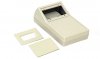
How does one mount a 16x2 character module on an enclosure like this? If it was flat, the std solution would have been to use spacers of the desired height and screw them on the PCB itself. But at an angle of 24deg, do they sell spacers that are flat at one end (flat against the PCB) and angled at the other (against the LCD module)? Or there's a better way to do this?
 

Attachments

  • HPS.jpg
    HPS.jpg
    25.2 KB · Views: 393
If you mounted the LCD pcb using standard spacers, the LCD pcb would be angled at the same angle of the enclosure window, ie 24deg, which is what you want.

I think you are seeing a 'problem' that dosnt exist.:)
 
That is correct, the display PCB mounts to the "window" bit using standard spacers; if the "window" is at an angle, so will be the display. But if your design includes all circuits and the display on one PCB that is mounted horizontally, then the case you need is the one that has the horizontal "window"..
 
Unfortunately, the 4 holes on my LCD module, spaced at 75mm apart (hole centre to hole centre) do the fit the ones on the enclosure. The enclosure specs here :
**broken link removed**

Any ideas on how I can overcome this?
 
Unfortunately, the 4 holes on my LCD module, spaced at 75mm apart (hole centre to hole centre) do the fit the ones on the enclosure. The enclosure specs here :
**broken link removed**

Any ideas on how I can overcome this?

You could drill and bend, two 22gauge Aluminium [1.5mm] brackets.
One bracket for each end of the LCD pcb.

If you design and bend the brackets to suit the height of the LCD, you will not require spacers.

Do you follow that OK.?
 
Another way would be to use spacers and two flat strips of plastic or metal. The flat strips would be attached to the display with appropriate spacers. The flat strips would then could be drilled to match up for the "inset" mounting holes of the top cover.

Going to a horizontal case will probably be no better. Using a horizontal hammond instrument case, for a 20x4 display, was just as challenging.
 
Guess having brackets of some sort would be the way out.

I am wondering if plastic spacers could be had. At the appropriate height, cut the top end at an angle of 24deg (now spacer1a and spacer1b). Put the module between both spacer 1a and 1b and screw all three together. That way, we can mount the LCD module onto the PCB board. Of course, that's how it plays in my mind. Not sure if such spacers exist or if it is practical

Get some nylon spacer tube, 2.5mm IDia, use a utility knife, cut at 24deg.
 
Status
Not open for further replies.

Latest threads

Back
Top