Hello
I have a problem with an analog isolation, I want to isolate a DC signal various between 0 - 60mV.
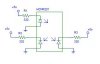
I use a HCNR201 and the schematic of the datasheet (page 9, figure 12B)
http://www.datasheetcatalog.org/datasheet/hp/HCNR200.pdf
When I check the voltage at the end of the circuits a have always the same voltage.
I want to check the component step by step to make sure it's not damaged. What's the easiest way to do it?
If I undestand right when I force some current through LED (i.e 12mA) the output diodes should conduct the current if are properly supplied, am I right?
Any help would be appierciated as I've spent lot of time and still have nothing.
I have a problem with an analog isolation, I want to isolate a DC signal various between 0 - 60mV.
I use a HCNR201 and the schematic of the datasheet (page 9, figure 12B)
http://www.datasheetcatalog.org/datasheet/hp/HCNR200.pdf
When I check the voltage at the end of the circuits a have always the same voltage.
I want to check the component step by step to make sure it's not damaged. What's the easiest way to do it?
If I undestand right when I force some current through LED (i.e 12mA) the output diodes should conduct the current if are properly supplied, am I right?
Any help would be appierciated as I've spent lot of time and still have nothing.
")
 ? I'm in south of UK