Continue to Site

Welcome to our site!

Electro Tech is an online community (with over 170,000 members) who enjoy talking about and building electronic circuits, projects and gadgets. To participate you need to register. Registration is free. Click here to register now.

  • Welcome to our site! Electro Tech is an online community (with over 170,000 members) who enjoy talking about and building electronic circuits, projects and gadgets. To participate you need to register. Registration is free. Click here to register now.

Analog Isolation help

Status
Not open for further replies.
ok i will try to invert PD1 and PD2.

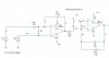
what do you mean when you say "The LED is shown the wrong way around in your diagram." I have invert anod and cathod of the LED ? because in the datasheet i see this schematic (in attach files)

my location :confused: ? I'm in south of UK :)

Im also in the South of UK.!
If you would like to send the project to me by post, drop me a PM.
I would be happy to check it out for you.

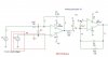
Look at this image from the datasheet and compare it with image you have just posted.
 

Attachments

  • esp01 Jun. 01.gif
    esp01 Jun. 01.gif
    4.2 KB · Views: 197
  • esp01 May. 29.gif
    esp01 May. 29.gif
    8.3 KB · Views: 193
Last edited:
hi,
This dwg has the pin numbers.
 

Attachments

  • esp01 May. 29.gif
    esp01 May. 29.gif
    8.4 KB · Views: 276
hi, i have test the circuit with the ;odification, i always have 200mV at the output,
all of my supply are good.

It's probably that the HCNR201 is broken
 
hi, i have test the circuit with the ;odification, i always have 200mV at the output,
all of my supply are good.

It's probably that the HCNR201 is broken

hi,
It sounds like its died, I would keep it on the shelf and get a replacement.

Farnell carry them is stock.
 
hello

I have receive two new HCNR201, and i have some news about my circuit !!

the good news is that my circuit works but just for about 20-30 second.
After, I need to shut off the supply and wait a few moment before shut on again the supply and the circuit works for 20-30s.
After this time, i have no voltage at the output. i have try with just one HCNR201, because i don't want (just in case) to damage the second HCNR201.
Do you know where is the problem ? because i have no idea


the second problems is that i have a linearity until 50mV. when my input is bigger than 50mV in the output i have already 500mV, i think that i need to change a resistor (maybe 1.2k by 1k).

So i begin to be happy because the circuit begin to works :) but the first problem is a big problem :(

thank you.

hi,
Post a full circuit showing the component values and the power supplies.:)
 
thank you for your fast answer :)

my circuit is in attach file, for the power supply i use a charger of 5V. I have forget to say that to beginning i use juste one supply for everything, maybe it's the problem, because normally we need two supply.
 

Attachments

  • schema.JPG
    schema.JPG
    28.8 KB · Views: 276
Last edited:
thank you for your fast answer :)

my circuit is in attach file, for the power supply i use a charger of 5V. I have forget to say that to beginning i use juste one supply for everything, maybe it's the problem, because normally we need two supply.

hi,
Look at the edited image showing the HCNR pins.

According to the datasheet, for a unipolar device, pin 4 should be at ground.
Read datasheet page 1-431, bottom left column, stating unipolar operation.

For bipolar operation a dual opto is required.

Measure the LED current while the device is working, use a series milli-ammeter.

EDIT:
Exactly what current is the V1-2 shunt resistor measuring,? 'ac', 'dc' and how 'clean' is it.?
 

Attachments

  • schema.JPG
    schema.JPG
    35.2 KB · Views: 336
Last edited:
ok thank you for this information,

i don't know that the pin 4 must be connect to the ground I will try
 
ok thank you for this information,

i don't know that the pin 4 must be connect to the ground I will try

In my edit for the last post, Im asking what is the current being measured.?

If it has high transients due switching inductive loads, there should a filter/limiter before the PD1 connections.
 
hi

sorry for the double post, but i just want to say:

It's works !!! i'm happy I want this for a long time :)

now i think i will use a divider before the analog optocoupler because i have a bipolar operation as you say !

Thank you very much Ericgibbs.
 
hi

sorry for the double post, but i just want to say:

It's works !!! i'm happy I want this for a long time :)

now i think i will use a divider before the analog optocoupler because i have a bipolar operation as you say !

Thank you very much Ericgibbs.

Well done,:)

I would measure the LED current when the unit is working, that will give you an idea which part of the response its working over.
Refer to the LED mA graph on the datasheet.
 
Last edited:
ok I will try to measure the current in the LED, but i'm not sur that my multimetre can read small current

I think that i will do this tomorrow and i will post my result after.

thank you again :)
 
Hi, i Have mesure the current in the LED

I have a current vairous between 0 to 30uA i have change R1 to 2Kohm to have 30uA when i have +60mV and it's works.


that's all bye and thank you again
 
Hi all

I found this thread searching for information on the use of the HCNR201. I note that the final diagram which worked is as per the datasheet 12b. However, the datasheet does not identify values for the capacitors across the op amps. How were the values in this thread (0.33uF input and 10nF output) arrived at? Also, the LED current limiting resistor is not defined in the datasheet. 330R is obviously a very typical value for a standard LED but is this correct for the HNCR201?

Thanks in anticipation

Peter
 
Status
Not open for further replies.

Latest threads

New Articles From Microcontroller Tips

Back
Top