Continue to Site

Welcome to our site!

Electro Tech is an online community (with over 170,000 members) who enjoy talking about and building electronic circuits, projects and gadgets. To participate you need to register. Registration is free. Click here to register now.

  • Welcome to our site! Electro Tech is an online community (with over 170,000 members) who enjoy talking about and building electronic circuits, projects and gadgets. To participate you need to register. Registration is free. Click here to register now.

(Analog) Is this a D flip-flop?

Status
Not open for further replies.

genxium

New Member
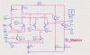
This component is from the ADS 2008 example, I don't quite understand how it works clearly.

By far I think that if D=0,CLK=1 , then the collector current Ic of BJT1 is small, resulting in that Vc of BJT1 is High, hence Vb of BJT14 is High and BJT14 is active, so [LATEX]\bar{Q}[/LATEX]=1.

But I have no idea how to figure out Q when D=0, CLK=1, can anyone give me a hint?
 

Attachments

  • D flip-flop.JPG
    D flip-flop.JPG
    119.4 KB · Views: 452
Sort of. The second diff pair form the latch. 'Clk not' must stay high during idle to keep second diff amp latch going or it will go to undefined state.

There may be a race condition when transitioning allowing a momentary undefined state if the rise time is too slow or 'Clk not' releases slightly before D goes high.

Thank you so much for such a quick reply! ^_^

Can you help me with another question also about this figure? I wanna know if the left most 2 BJTs with collector resistor are working as inverters here(if 'CLK' is high)?
 
Q follows D when clock is high. When clock goes low, Q latches in current state. It's a D latch.
To make an edge-clocked D FF, you need two stages cascaded, with the clock inputs on the second (slave latch) inverted relative to master latch.
When clock is high, the voltages at the collectors of the input differential pair will indeed be the complements of their respective bases,
 
Status
Not open for further replies.

Latest threads

New Articles From Microcontroller Tips

Back
Top