There is no such thing as a generic Mosfet. each one is different even if they have only one part number.@audioguru: That's a good question. This same setup would probably not work since its not a generic setup. For different MOSFET's, won't you just bias it accordingly?
they have a range of voltages that turn them on.
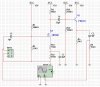
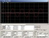
Then the circuit might oscillate at a very high frequency due to the high stray capacitance.I spaced them out so it can be simpler for me to visualize things.
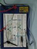
Many high frequency circuits do not work if they are built on a breadboard.
Many years ago I made a circuit on a breadboard. It didn't work. Then I made it on a compact stripboard and it worked perfectly. I never used a lousy old breadboard again.
")