Continue to Site

Welcome to our site!

Electro Tech is an online community (with over 170,000 members) who enjoy talking about and building electronic circuits, projects and gadgets. To participate you need to register. Registration is free. Click here to register now.

  • Welcome to our site! Electro Tech is an online community (with over 170,000 members) who enjoy talking about and building electronic circuits, projects and gadgets. To participate you need to register. Registration is free. Click here to register now.

Amplify 0.1-1mV from a bridge for Arduino use

Status
Not open for further replies.

Pcba

New Member
I had no success the last few day to make a meaningful progress and am desperate for help!

What I want:

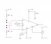
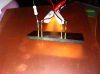
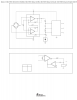
Measure copper foil resistance with the 4 probe methode, like here:

figure2.gif

I put about 1A on the outer pins - and on the inner pins I measure 100-800µV (with a multimeter).

From here I like to feed that voltage to an instrument amplifier (I tried AD623 and INA126) - and I am stuck at that step.

Maybe InAmp is not the best way and there are better ways? I need an voltage that I can read with Arduino. How is not too important, hopefully not too expensive though.

What you suggest?
 
An instrument amp is the right tool for that job and should work.

You didn't describe what problem you are having. That makes it hard to help you to solve it.

Also, please post a schematic of what you are doing.
 
An instrument amp is the right tool for that job and should work.

That was the first thing I wasn't certain about. I attached the circuit.

I use INA126 (as in the circuit) - or AD623 (then GND instead of -4.5V)

What I do:

I measure Out (pin 6) against GND
Set Ref (against GND) to what I measured
OUT to REF is now <10mV

When I now measure different copperfoils - which should be 100 and 800mV respectively the output shows always the same (-2.7V) (I forgot which IC, it's not in front of me right now).

Rg is 120R which makes G=830 (AD623) or G= 670 (INA126)

I wonder if my circuit idea is wrong, or of the ICs are defect (they did got hot sometimes)

Another basic question I have, are those two InAmps able to handle low voltage below 1mV?
 

Attachments

  • 4p.jpg
    4p.jpg
    38.3 KB · Views: 848
Last edited:
hi P.

The 3R9 resistors are a low value,?

When you say copper foils, what is their approx resistance.?

You could be exceeding the permissible CMV on the IA inputs, this would make them overheat.

Show how the foils are connected.

E
 
The 3R9 resistors are a low value,?

2 times 3R9 = 7R8

So with 9V I get a bit over 1A.


When you say copper foils, what is their approx resistance.?

It's very near 0 - I presume below one mOhm. I testing different foil thickness half oz to 5 oz.

You could be exceeding the permissible CMV on the IA inputs, this would make them overheat.

I tried a lot of different setups, and sometimes the ICs got hot. There is a chance that I did some grave errors. I forgot the current, I think it was about 0.05mA, need to look that up later.

Show how the foils are connected.

Exactly as in the very first image.

4 test pins
I soldered the 3R9 to the outer pins
The inner pins I connect to the InAmp

The 4 pins are drilled into a piece of insulation material. I simply push that 4-pin construction onto a piece of copper clad laminate.
 
Why don't you use a Wheatstone bridge and use two ADCs, or differential amp and one ADC, to measure the voltage of point B and D and do the math:

View attachment 74825

https://www.electro-tech-online.com/custompdfs/2013/07/slyp163.pdf

Isn't a 4 probe something similar to a bridge? I measure the voltage at 2 points now. I was thinking about ADC too, but I am unclear about their input range, and whether they are suitable for down to 50 µV. I don't need extreme fine resolution. 50-800µV in ~20 steps is fine.
 
Isn't a 4 probe something similar to a bridge? I measure the voltage at 2 points now. I was thinking about ADC too, but I am unclear about their input range, and whether they are suitable for down to 50 µV. I don't need extreme fine resolution. 50-800µV in ~20 steps is fine.

Hmm.. yes. I didn't think that completely through. The resistance you are measuring is very small. You would need to measure the current (or voltage) between points D and B very accurately. Dave Jones has made a nice circuit to measure very small currents (down to picoAmperes).

Take a look at the project page with schematics:
https://www.eevblog.com/projects/ucurrent/
And video about the design:
https://www.youtube.com/watch?v=g7b5YZENvjY

The "heart" of the circuit is the MAX4239 "ultra-high precision, near-zero offset" op-amp.

The arduino "analog read" is a 10 bit ADC. With 1V reference voltage you get ~1mV resolution.
 
Last edited:
hi Pc,

What tolerance are the 3R9 resistors.?

With a gain of ~800, an imbalance in the 3R9's could easily give ~3mV which would be 2.7V on the output.

Also I assume you are inserting/connecting two identical copper films in the other half of the bridge?
 
What tolerance are the 3R9 resistors.?

I need to check that. They were 'around' and not for that purpose, rather high I think.

With a gain of ~800, an imbalance in the 3R9's could easily give ~3mV which would be 2.7V on the output.

But isn't pin 2 + 3 from the InsAmp not measuring the difference between 2 + 3? Hence it wouldn't be important, or? I have the 2 R there just to limit the current, otherwise it would simply short the powersupply. Like, 35µm/1oz copper foil is simply the normal raw material for PCBs. Size I use is about a sheet of paper = A4.

Also I assume you are inserting/connecting two identical copper films in the other half of the bridge?

I have 4 probes in a line, which I press onto the copper sheet. I do a pix later.....
 
hi Pc,
Look at this LTSpice simulation.

Note the polarity of the 3R9 supply, also they are 0.01% tolerance.

IMPORTANT: when the foil is not in contact with the voltage sense probes, the non inverting input of the AD623 will exceed the specified voltage and the AD623 will get hot and die.!!!

The metal used for the probes must also not produce a voltage when in contact with the copper foil, use copper probes.

Note the resistance of the foil in the Sim is only 1.7milli-ohms, which has a voltage drop of ~1mV.

For a 500mV Vout voltage.

E.
 

Attachments

  • AAesp01.gif
    AAesp01.gif
    29.5 KB · Views: 319
Back were the action is:

the 3R9 are 'J' = 5%

Another general question: what voltage I adjust REF to? To the voltage on OUT? Or to 2 or 3?

I like to do a general test if my InAmps still work, you have any simple circuit I can setup for testing?

I like to add that it seems whatever Rg I use, the output does not seem to change (I used a potentiometer before).

Right now I did a test with a photodiode and also get no fluctuation with light intensity.

You posted while I was writing:

IMPORTANT: when the foil is not in contact with the voltage sense probes, the non inverting input of the AD623 will exceed the specified voltage and the AD623 will get hot and die.!!!

See my picture of the probes. When the probes are not in contact with copper both probes are open. It's of course very possible that not all probes connect at the same time and there could a ms were one of the sensing contact has either full +V or full -V/GND.
 

Attachments

  • cu_test.png
    cu_test.png
    619 KB · Views: 273
Last edited:
Back were the action is:

the 3R9 are 'J' = 5%

Another general question: what voltage I adjust REF to? To the voltage on OUT? Or to 2 or 3?

Using the voltage polarity to the 3R9 resistors as I have shown, the Vref can be connected to 0V


I like to do a general test if my InAmps still work, you have any simple circuit I can setup for testing?
To test the AD623, connect the two 3R9 together and join both AD623 inputs to the junction of the two 3R9's ,, the AD623 Vout should be close to 0V


I like to add that it seems whatever Rg I use, the output does not seem to change (I used a potentiometer before).
I suspect the AD623 is in saturation, thats why the Vout is fixed at -2.7V

Right now I did a test with a photodiode and also get no fluctuation with light intensity.


hi
Try the test I have described above.

Let me know what you measure as Vout.
 

Attachments

  • AAesp02.gif
    AAesp02.gif
    6.9 KB · Views: 938
I followed your circuit closely. I used 100nF instead 10micro, other is same.

With no copper (2+3 = shorted but seen together they are open) I get shaky +30mV, plus funny spikes up to 1.5V
On copper I get +1.66V

I thought the spikes are due to my cheap Chinese power supply, but I also get them when I use a 9V battery.
 

Attachments

  • image.jpg
    image.jpg
    97.6 KB · Views: 285
hi,
Your scope shows a 50Hz spike which I suspect us due to the IA picking up mains interference on its inputs.

How long are the wire leads from the IA inputs to the 3R9 resistors?

Also note if the 3R9 resistors are wire wound resistors , which is usual, the resistor windings will pick up radiated 50Hz mains and other interference.

Did connect the IA for the test as shown in my last posted circuit.??
 
Yep, connected as in the drawing. Have to say that the wires are 30cm (1feet) or so, and resistors are wire type, 10W. Since the spikes are also happen when I use battery I think it's the wires rather then the resistors - which are not connected when the probes are not on copper. When I disconnect pin 2 then the spikes are gone, pin 3 has no effect.

It's getting close to midnight here, I continue tomorrow.

From what you see so far, could it be that the ad623 is defect or is it within range?
 
I had another try. Instead of the 3R9 I used 2R 1% 5W. Supply voltage 5V.

Open the output was again low, about 10mV (not counting the 50 Hz spikes), under load it was 2.7V. Both 5V were on the same rail. When I separated them and used a lower pin voltage I noticed that open and load voltage don't change. Even going down to 0.5V.

I also changed the 120R Rg to a pot - again not change to whatever turn e pot too.

I think I wil order some new AD623
 
I

I think I wil order some new AD623

hi,
It is very possible that the AD623 is damaged.

I would add a 10K resistor in series with the non inverting and inverting inputs of the AD623, this will prevent excess input current damaging the IA.

Its important as I said previously not to allow the inputs of the IA to exceed the specified input voltage.

Look at this image.
 

Attachments

  • AAesp03.gif
    AAesp03.gif
    86.7 KB · Views: 299
again not change to whatever turn e pot too.
You are trying to measure down to 100μV. The specified input offset of the IA can be up to 200μV, so that may result in the amp saturating if the gain is high and will give inaccurate measurements. Do you have any offset-nulling facility in your setup?
 
@ericgibbs

Will get new AD623 soon. When the measure source - and the supply voltage is from the same source then 0.3V over the source is pretty much impossible, or? (This said, I did some test with a 9V battery as bridge source..... so it is possible)

Since I use probes to connect, and since it is very likely that not all probes connect at the same time, and therefore pin 2 and/or 3 can get full +V or GND - but not +V + 0.3 - there is no harm - or? I will put some R in the K range in front of the pin 2 + 3 anyway though.

IC and bridge supply can be from the same source, or?

@alec_t
What is the minimum/maximum V the AD623 can handle on the inputs? I have no "offset-nulling facility". I have the REF (5) to GND. I did see some designs that use a ref voltage IC (i.e.: http://www.ti.com/product/ref1004-2.5 ) - is that something I should try?

My next plan, after I get the new ICs:

I will make a classic 4 R wheatstone bridge (maybe with 1K resistors)
Will substitute 1 R with a same range Pot
Will put protection R in front in IC pin 2+3

I am not too concerned by the 50Hz interference. Will be hard to avoid on a breadboard design I think.

Any comments so far?

I will try that tonight.

Added: A circuit with an similar INA126 were pin 5 goes to a ref1004 Source/
 

Attachments

  • INA126-circuit-9.png
    INA126-circuit-9.png
    11.7 KB · Views: 660
Last edited:
Status
Not open for further replies.

New Articles From Microcontroller Tips

Back
Top